SEFT simulation - problems with parameters
-
I am currently doing some focused ultrasound simulation. The goal being to reach a precise part into the brain. I did your tutorial which worked fine but now I would like to change a bit the SEFT parameters.
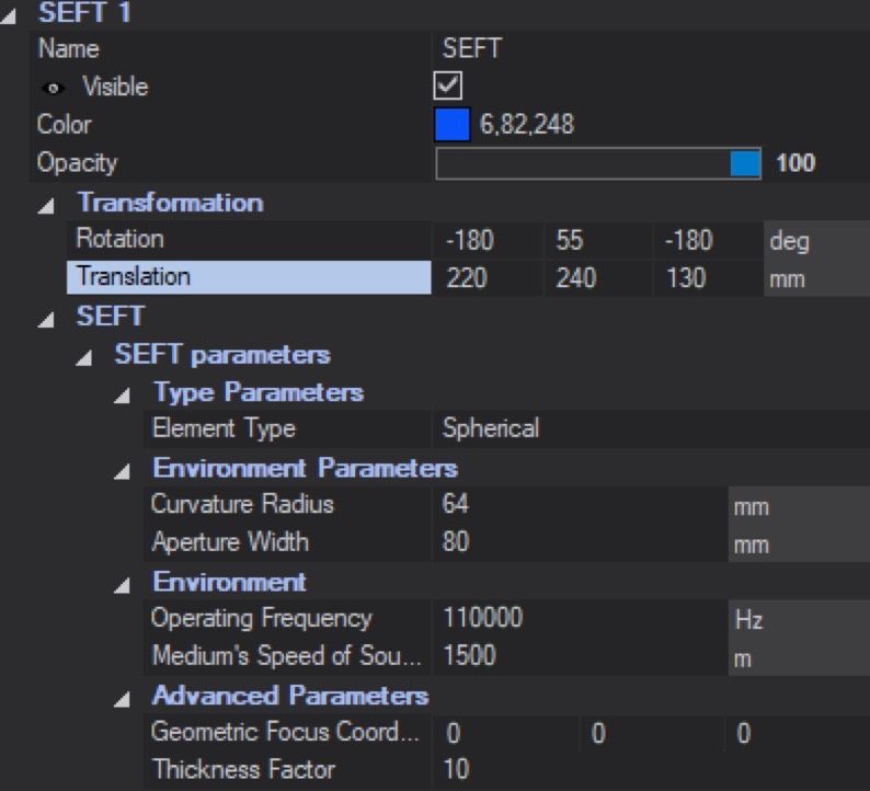
I wanted to reproduce a transducer where I have the curvature radius, the aperture width and the focal depth which are 3 different values. I know how to change the 2 first but then when I remove parametrization of the SEFT to be able to move the focus it doesn't keep my exact values. How should I do that ?
And I have a some other questions:
- Is it possible to measure (and after visualize) the intensity over the time for my simulation?
- What is the difference between the setup frequency and the Environment Operating frequency?
Thanks for the help !
-
-
I don't understand the question. You can change the curvature radius and aperture in the GUI. The point created in the SEFT model corresponds to the geometric focus (essentially the curvature radius), this is not the focal depth. You'd need to run the simulation to figure out where the max will be or use some analytic formula.
-
In Sensors in simulation you should be able to toggle from 'Frequency' to 'Frequency and Time Domain Recording' and then you can select how many snapshots you want to record and from what time to what time
-
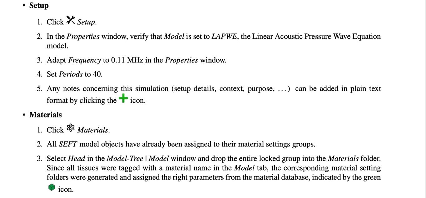
Setup frequency is the sinusoidal frequency at which the source is excited.
-
-
-
I don't understand the question. You can change the curvature radius and aperture in the GUI. The point created in the SEFT model corresponds to the geometric focus (essentially the curvature radius), this is not the focal depth. You'd need to run the simulation to figure out where the max will be or use some analytic formula.
-
In Sensors in simulation you should be able to toggle from 'Frequency' to 'Frequency and Time Domain Recording' and then you can select how many snapshots you want to record and from what time to what time
-
Setup frequency is the sinusoidal frequency at which the source is excited.
@montanaro The setup frequency and the environment operating frequency should be the same? (I found that these two frequencies are the same and set as 110 KHz in the tutorial)
What is the impact on simulation results if the setting is different? -
-
I don't know what environment and operating refers to. The simulation frequency refers to the source signal from the transducer (I assume this is what you mean with operating frequency) ... I don't know what environment frequency is, maybe you mean the frequency at which the output is evaluated?
The default acoustic solver (LAPWE) solves a linear equation, therefore a source pulse at a given frequency will give you an output oscillating at the same given frequency. The output of the acoustic solver is the magnitude of the pressure at that oscillation.
If you want to look at the energy content for other frequencies you will need to use a nonlinear solver and materials would then need to have some nonlinear properties. Typically you don't need this, but it depends on what physical phenomena you're interested in modeling.
@montanaro Sorry for the misunderstanding.
The environment operating frequency was setting in the SEFT parameters. (SEFT is in the Explore window)

Setup frequency was in the 「Setup」

-
Ah I see ... Environment frequency was just used in creating the transducer (I think it doesn't actually do anything, it's just a parameter such that if you drag and drop the SEFT into the Simulation object then it will automatically set the simulation frequency to the correct value). Setup frequency is just the frequency at which the sinusoidal sources in your simulation are operated.
Essentially, only the Simulation (Setup) frequency matters
@montanaro Hi Montanaro
I noticed that only one setup frequency could be set, even I dropped the two transducers into the simulation object,
So If two transducers are used in the simulation, could I set the different frequencies for these two transducers?
-
You can but it's a bit complicated (not too much though)
Typically, in these simulations you excite the transducers at a given frequency for a certain number of periods. The simulation is run in the time domain but the final results you see are the FFT of the last period of simulation at the simulation frequency with the assumption that you have reached steady state in your simulation.
This kind of final analysis doesn't make sense if you have multiple sources operating at different frequencies in your simulation.
What you can do is this:
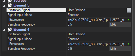
In sources, you are given the option for 'User defined sources', and that can take either equations or a text file. You can set each source to it's own sinusoid. Please note that you should set your 'setup frequency' to the highest frequency available since I think this value is also used to automatically set the time step (I'm not 100% about this but I'd do it anyways to be safe)
You can then make recordings in the Time domain only (not frequency domain) and chose the number of snapshots (careful, this will consume a lot of hard disk memory if you have too many snapshots)
Hope this helps
@montanaro Hi Montanaro
Thanks for your useful suggestion.

-
May I know that what the sampling frequency mean here when I changed the excitation signal from 'Sinusoidal' to 'User Define'.
-
what is the difference between sampling frequency and setup frequency.
-
The expression sin(2pi0.75E9*_t) + 3sin(2pi1.25E9_t) of the 'User Defined' is the same with 'Sinusoidal' of excitation signal.
-
In the 'Sinusoidal' mode, two parameters (amplitude and phase) can be set up, and in the 'User Defined' model, two parameters (expression of equation and sampling frequency). what are difference of these two models.
Thanks.
-
-
- I don't remember so well, but I'm pretty sure it's 1/timestep used to discretize / sample the signal. (Note that this is used to create a list of time points and pressure signals, but the acoustic solver then again reinterpolates this signal to it's own time step that is calculated from the Setup Frequency)
- Setup Frequency is mostly ignored now that you have user defined source, it was mostly used as a frequency of the sources and for the final FFT analysis. However, if I remember correctly it is used to calculate the time step used in the solver, so make sure it is set to the highest frequency available in your sources
- That expression was just a random signal to give the user an idea of how to input expressions. It seems in your case you want Element 5 to be sin(2 * pi * 0.5E9 *_t) and Element 6 to be sin(2 * pi * 0.75E9 *_t) if you want to excite one transducer at 500 KHz and the other at 750 KHz
- User defined sources sets an equation which is then sampled / interpolated at that sampling frequency (fs = 1/dt)