What is the mismatch efficiency?
-
When I moved to the radiation report on Analysis tab, I found mismatch efficiency, but don't know what it means. I would like to know Total available power as well.
Thank you.
@rose I would recommend reading that section of the Sim4Life Manual:
2.5 EM FDTD (Finite-Difference Time-Domain) Solver » 2.5.1 EM FDTD Simulation Theory » 2.5.1.4 Power BalanceIn particular, this flow chart taken frem IEEE 145-2013:
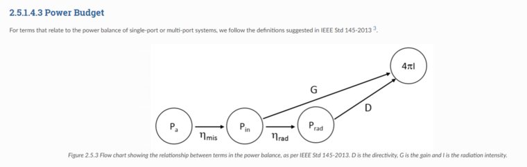
where
 is the mismatch efficiency (ratio of input power Pin to total available power Pa)
 -
@rose I would recommend reading that section of the Sim4Life Manual:
2.5 EM FDTD (Finite-Difference Time-Domain) Solver » 2.5.1 EM FDTD Simulation Theory » 2.5.1.4 Power BalanceIn particular, this flow chart taken frem IEEE 145-2013:
where
is the mismatch efficiency (ratio of input power Pin to total available power Pa)@sylvain Thank you! It really helped.
I'm working on the dipole simulation and I got a proper(I mean reasonable) results. After the simulation, I changed some parameter and simulated.
Although I changed only the length of the model and frequency from 0.3GHz to 3.0GHz, Total Available Power(TAP) changed from 1.3W to 29.2W and Gain has doubled.
I would like to know why it happened.
-
@sylvain Thank you! It really helped.
I'm working on the dipole simulation and I got a proper(I mean reasonable) results. After the simulation, I changed some parameter and simulated.
Although I changed only the length of the model and frequency from 0.3GHz to 3.0GHz, Total Available Power(TAP) changed from 1.3W to 29.2W and Gain has doubled.
I would like to know why it happened.
@rose your simulations are most likely done with a 1V voltage at the excitation source (that's the default setting). This is perfectly fine from a numerical point of view, but in practice (e.g., if you wanted to compare with measurements) you probably want to normalize your results. In the Far Field Sensor, for example, you can normalize to a Total Available power of 1W (say). This way, you will be comparing apples to apples.
That will not change the value for the Gain, though (since it is a power ratio, independent of scaling). This must come from either a difference in some aspect ratio of your dipole, or simply that you did not change the dimensions in the same proportion (1/10th) as you changed the frequency.
Hello! It looks like you're interested in this conversation, but you don't have an account yet.
Getting fed up of having to scroll through the same posts each visit? When you register for an account, you'll always come back to exactly where you were before, and choose to be notified of new replies (either via email, or push notification). You'll also be able to save bookmarks and upvote posts to show your appreciation to other community members.
With your input, this post could be even better 💗
Register Login