LF magneto static vector potential solver
-
Hello,
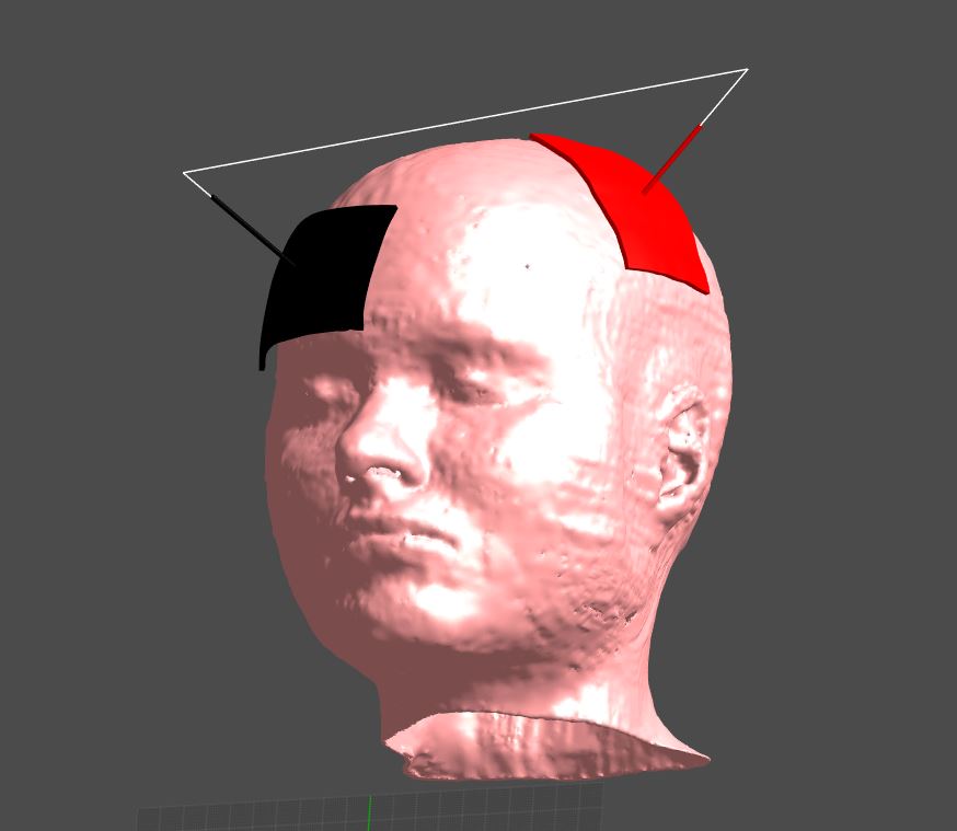
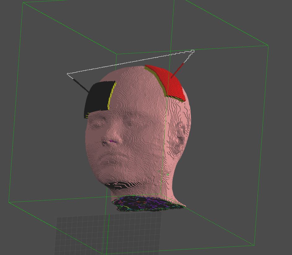
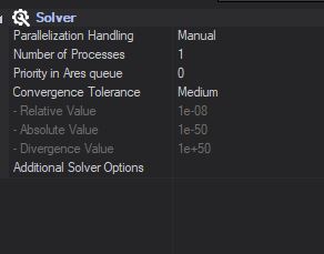
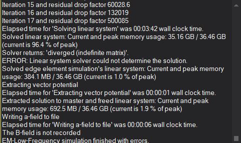
I'm trying to simulate exposure of MIDA model with tDCS electrodes. The two electrodes (anode and cathode) are perfectly shaped on MIDA's head and must be energized with a certain current intensity. To do so I'm using the LF magneto static vector potential solver. The two electrodes are modeled as PEC and a wire current source connects the two. Default properties of the solver are used. With this set up, the simulation fails and returns the error: "diverged (indefinite matrix)". Can I have some help understanding what I'm doing wrong?
I attach some pictures that might be helpful to understand the problem.Thank you very much,
Micol
-
Hi, the Magneto Quasi-Static solver basically computes the electro-magnetic field generated by a known current source. In practice, this current source has to be a closed wire. If not, the current field is not divergence-free and the equations diverge.
This is what is happening in your case, I think.Instead of using the MQS solver, you need to use the Electro QuasiStatic solver (the Ohmic Quasi-Static version, in fact). Give a fixed potential difference between the two electrodes as boundary conditions: the solver will compute the fields inside the head and, at postprocessing, you can compute the total current flowing from one electrode to the other (by integrating the current flux density J over a surface going across the head).
Once you know the relationship between voltage difference and current (in other words, the impedance) you can rescale all your results (E field, H field, SAR, etc...) thanks to the linearity of the governing equations. You can do that either at postprocessing, or by re-doing the simulation with a different voltage difference. -
Hi,
Thank you for the prompt answer. Guessing that the open wire could have been the problem, I've tried using the two "straws" on top of the electrodes as two cylindrical sources. In this way I can actually complete the simulation, however, even though I record the electric field, I only get vector potential A, B field and H field among the output quantities, how can I get E field and J, as well?For sure I will also try using the Ohmic quasi-static solver, as you suggest.
Thank you.
-
I don't think using cylindrical sources in that example will have the desired result in any case. If you were using the Magneto Static or Magneto Vector Potential solvers, you will indeed only get A, B and H fields as outputs (at frequency -> 0Hz, induced currents vanish). If you were using the MQS solver, you should have obtained E and J fields too (the values would not have been meaningful, I think, but still...). Please double-check which solver you were using.
In any case, you should use Ohmic Quasi-Static :)
-
I was using the Magneto vector potential at 1 Hz and I thought I could get E and J, but I couldn't.
However, I'm now using the ohmic quasi static. If I want to make sure that my eletrodes inject 1 mA, is it correct to evaluate the flux through the anode (red electrode in the model) instead of over a generic surface that crosses the head? -
Yes, the flux should be the same independent of the location of the surface: generic across the head, around the anode, or around teh cathode. Note, however, that the electrodes should be used as boundary conditions for the solver. This means that no fields (in particular no J) are calculated inside them, so you have to make sure that the surface you use to compute the flux does not go "inside" the electrode.
It probably works if you take the electrode itself to compute the flux but I am not certain (you can double-check by using different surfaces to compute the flux and see if you get similar results). -
Hello,
I've used the Ohmic Electro QS solver with the Dirichlet boundary conditions for the two electrodes, as you suggested and I've tried two evaluate the flux to find the proper scale factor. Doing so, my results don't agree with the intensities reported in previous letterature on tDCS. For this reason I've just tried to use the boundary condition "flux" and set 1 for the anode and -1 for the cathode, but I got this error: "Flux boundary conditions on objects not yet supported". Could you please help me to solve this issue?
Thank you very much
-
Flux boundary conditions only work for the faces of the computational domain (X+, X-, Y+, etc...). You need to use Dirichlet boundary conditions on the electrodes. Perhaps you can show how you computed the flux? It is easy to make a small mistake there.
-
Yes, of course. I attach a few pictures that might be helpful. I first dragged and dropped the anode in the over all field sensor and then I selected the flux evaluator. From the table viewer options I considered the total flux (ca 7.7 A in this case). Then I found the scaling factor necessary to obtain 1 mA instead of 7.7 A. Is this the correct procedure? I also checked using other surfaces and flux can be different, for example if I evaluate the flux over the sponge (yellow element, with a conductivity of 1.4 S/m) the flux is around 47 A. While considering a generic surface across the head is around 2 A.
Once again, thank you very much for your help, I really appreciate it

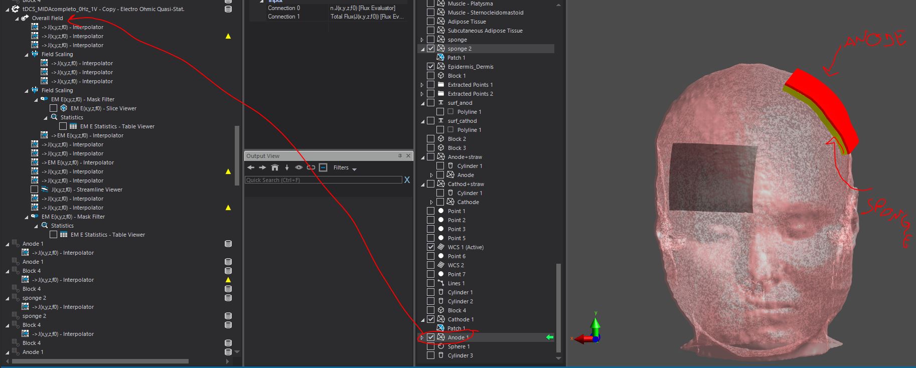
-
Your approach is the correct one.
There are a few caveats that could explain the discrepancies in the results (one should, of course, obtain the same current flux between anode and cathode regardless of the method used):- the surface used to compute the flux should intersect with all field lines between anode and cathode, once, and only once. An example might be a plane that cuts through the head, with one electrode on each side. Another possibility is to create a box that encloses one electrode. In your example, with the sponge, I think you might have current entering from one side and leaving through the other and would actually have expected a total flux of zero.
- the surface needs to be correctly discretized. For that, try to reduce the Minimum Edge Length property of the surface in the Explorer tree (after drag & drop), then Refresh Viewers, until the Total Flux value stops changing
- I am not sure what happens if the surface is also a boundary condition for the J field (as in the case of your electrode). Maybe there are some discretization issues there.
- In all cases, it often helps to visualize the flux of J on your chosen surface, by using the Surface Viewer
I hope this helps