How to setup a monopolar RFA for liver tumor
-
Dear Sim4Life community,
I am trying to build a model that consists of a human liver, a tumor and a monopolar electrode that consists of an insulator and the electrode, both set up by me, meaning that their properties were the default. The main problem is that in the end, the SAR is extremely low (10^-6) and I am trying to understand what the problem is. In the model tab, I assigned the materials to the ones I need for this project (electrodes made of platinium and insulator from polyethylene) so that I will be able to have the electrode in the boundary conditions (25V, Dirichlet) and also with the right electrical properties. Otherwise it doesn't let me run the simulation. Also, I set up the grid like the one in the tutorial (bipolar RFA) and the voxels with priority 1 for the tumor and 2 for the electrode. After the simulation, I select Slice Viewer for both E-Field and SAR, but my results are way off the ones expected. Any ideas what I can change in order to increase the SAR?
Thank you in advance.
-
Hey,
Did you check in the analysis tab if you normalized the field sensor to a certain input power (with which you would drive your electrode)?
This will most likely scale your fields to results you would expect in a realistic setup :)
Hopefully this helps.
Cheers -
Firstly thank you for your reply. I'm not sure I completely understand what you said, but if you mean that I should simply tick the optimization option in the analysis tab, unfortunately it didn't change something. I think that the problem is either in the boundary conditions or I need a ground because the E-field inside the tumor is 0. Regarding the boundary conditions, I have two of them, the one with plane x, y, etc and another Dirichlet boundary condition with the electrode (set at 25V). Should I include somehow the insulator as well? Or it's a matter of the circuit?
-
If you are using the low-frequency solver (in your case the electro ohmic-quasi-static solver, I suppose), then the electrode should not be modeled as an object with material properties (like platinium). Rather, it is only a boundary condition (the potential is set at 25V and no attempt is made to solve for the electric field inside the electrode). Check that this is the case, and that you have other boundary conditions that define the ground (e.g. 0V Dirichlet at the X+, X-, Z-, etc.. planes of the computational domain). Neumann boundary conditions will not work here.
Last, but not least, check that your simulation converged without errors. -
I'm using the quasi-static solver at 400kHz and your suggestions made things a quite better (SAR~10^-1) but still a lot far than the expected results that should be around 10^5. I assign the materials for the liver, the insulator (polyethylene) and I set the values for the tumor. The boundary conditions are as you suggested, 2 Dirichlet at 0 and 25V for the x,y,z etc and electrode respectively. Also, I have 3 voxels, 1) liver, 2) tumor and 3) electrode and insulator (priority 0,1 and 2). As for the grid, I have one for the tumor and one for the insulator and the electrode. Am I missing something that could majorly increase the SAR?
-
Here are a few suggestions:
- check that the simulation converges
- check the solver log for errors/warnings
- use the Ohmic quasi-static solver instead of quasi-static
- try to remove the "electrode" from the voxels (it should already be assigned as a boundary condition, I am not sure whether it should be in the voxels too)
- add some screenshots to your posts (settings, results, etc...) to help forum readers spot some any mistake you may have made
-
Quasi-Static Solver: The frequency is 400kHz, the potential is 25V, the tumor grid is 0.5-0.3, the applicator grid is 0.2-0.1 and the priority is 0, 1, 2 for liver, tumor and electrode respectively. I still cannot increase the SAR value (~1 W/kg) and I have almos the same results even if I remove the electrode from the voxels.
Ohmic Quasi-Static: The settings are identical to the quasi-static solver but I get 0 value for SAR after the simulation, with or without the electrode in the voxels.
The screenshots are from the quasi-static solver and I used the same for the ohmic quasi-static.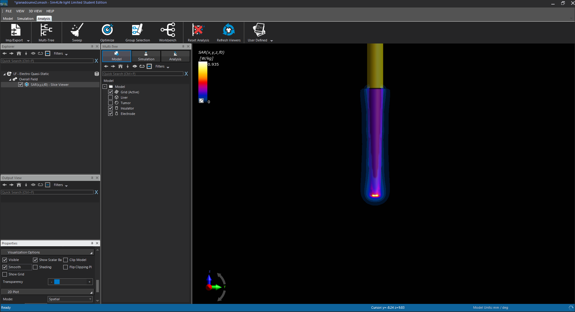
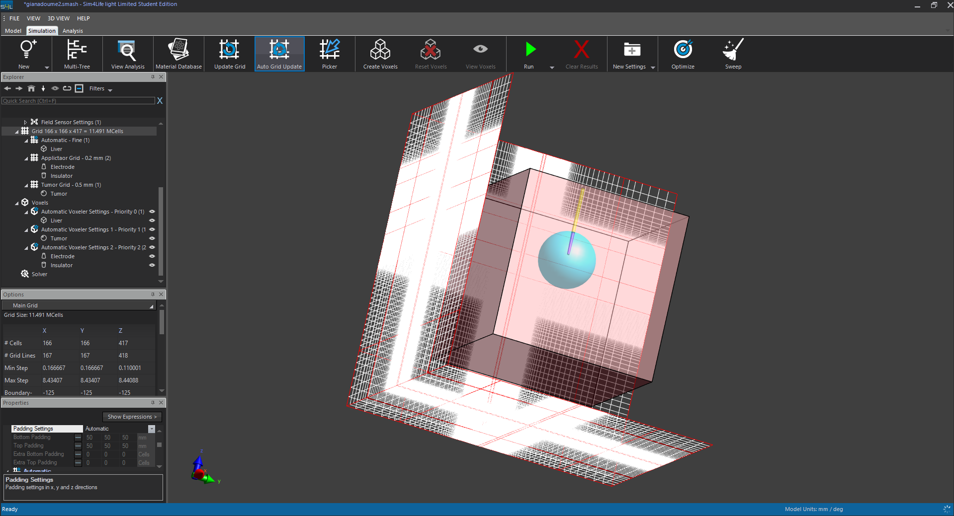
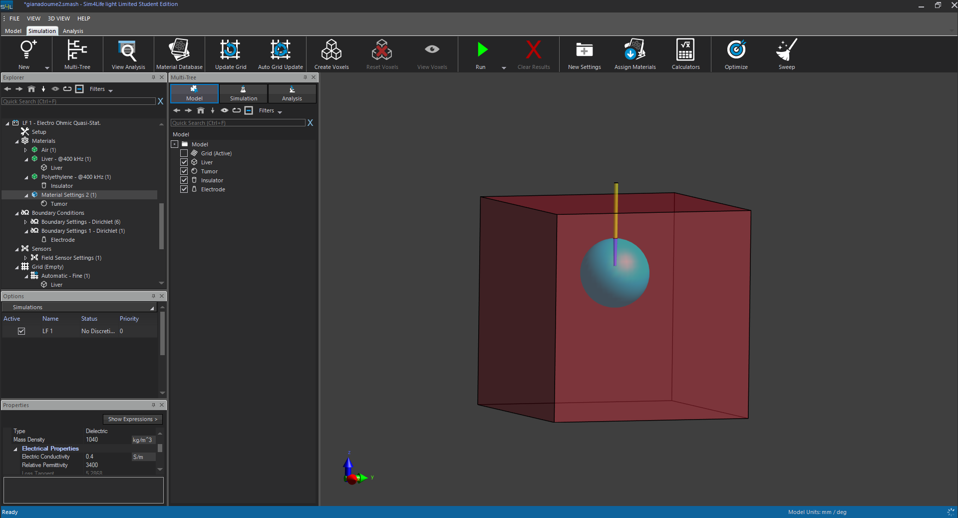
-
My guess is that you have a layer of air between the liver and your boundary conditions. This is acting like an insulator between the ground potential and your electrode. The ohmic current is therefore zero. There is a small (and usually negligible) displacement current (like a capacitive effect) which is picked up only by the Quasi-Static solver, hence the small SAR values.
To fix this, set the Padding setting of the Grid to Manual, with a small negative value to ensure that the boundary conditions intersect with the liver material. -
Thank you so much for your time and effort. Finally I have results fitting to my project (2.5*10^4 W/kg). I didn't think that the grid values were so important and that it needed to be "touching" the model (liver and insulator on top of liver). Once again thank you very much!
-
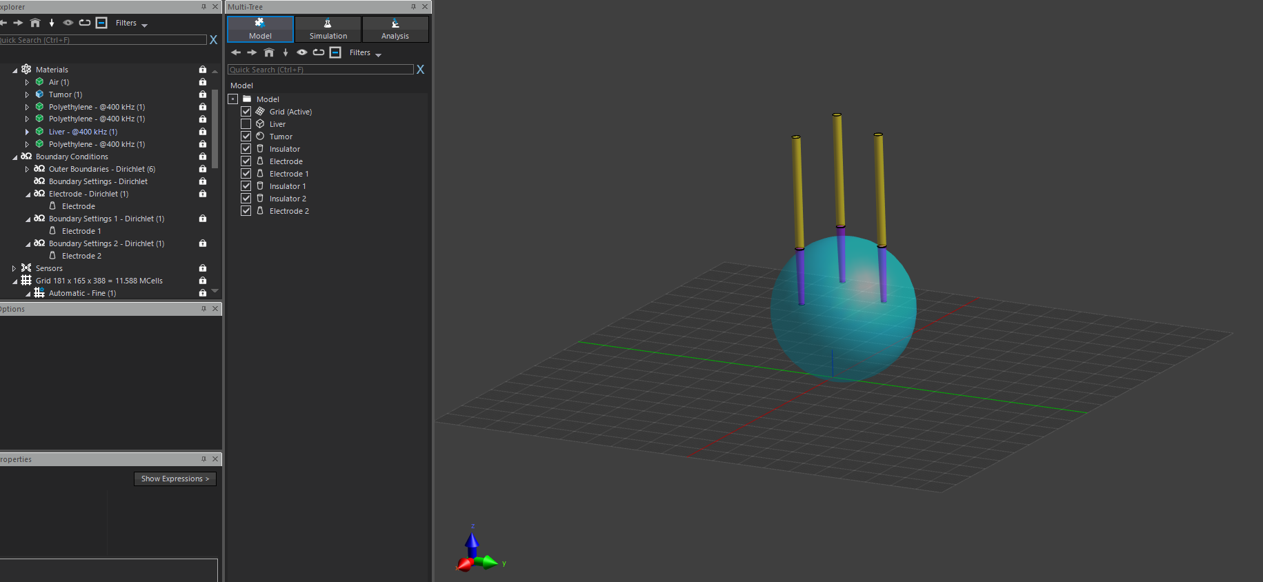
I seem to encounter a new problem with the simulation of this project. The goal is to have a 3 electrode model that emits RF radiation into a tumor. While the 2 electrode model works fine, meaning that both electrodes have E-field and SAR values, the 3 electrode model doesn't and I can't seem to find the problem. I tried to set it up exactly like the 2 electrode one, but it doesn't work. I get either 1 electrode working or 2 depending on the setup. Could you please have a look and maybe find the problem in my model?
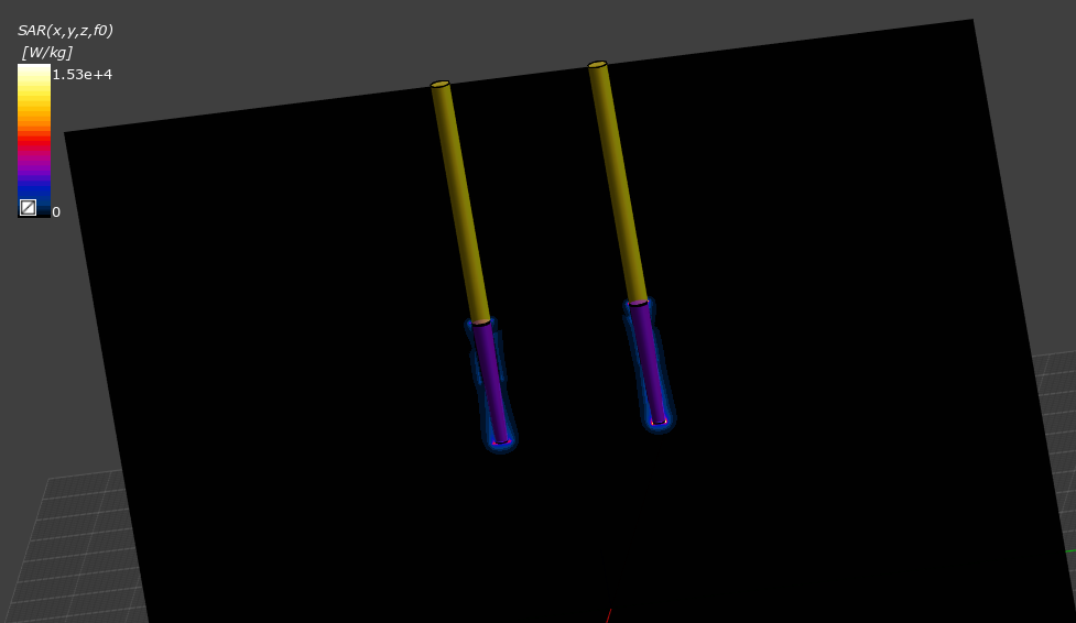
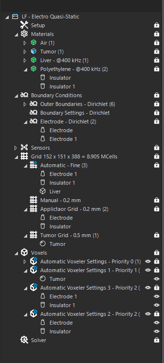
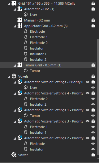
First 2 pictures are of the 2 electrode model (working) and the last 2 of the 3 electrode model in which only the Electrode-Insulator pair is working and gives SAR values. I know that the settings aren't the same, but even if I set it up exactly the same way as the 2 electrode model, the same problem appears.
!
