simulation with 10k spheres
-
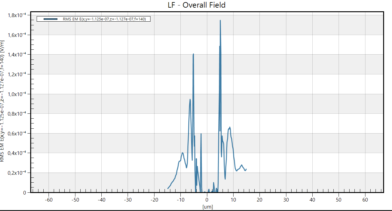
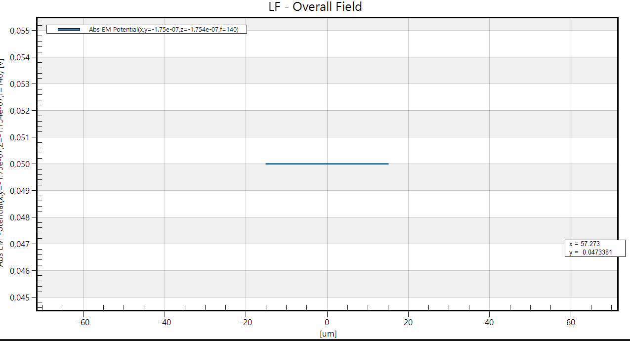
Hello, I have a problem with a simulation using low frequency electro ohmic quasi static. I drew 10,000 non-touching spheres, applied the same condition to each one and simulated the electric field generated inside a gray matter box. The electric field comes as in the picture, it could make sense. While the potential is flat and does not decay (I think it is wrong). I have tried with a box of gray matter much larger than the volume occupied by the nanoparticles, but the potential is always flat.
The frequency of the simulation is 140hz, the total diameter of the "big" sphere is around 10 um. Instead, each "small" sphere has a radius of 125nm.
Any suggestions are welcome!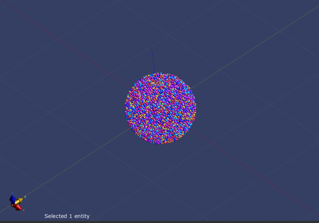
-
Hello, I have a problem with a simulation using low frequency electro ohmic quasi static. I drew 10,000 non-touching spheres, applied the same condition to each one and simulated the electric field generated inside a gray matter box. The electric field comes as in the picture, it could make sense. While the potential is flat and does not decay (I think it is wrong). I have tried with a box of gray matter much larger than the volume occupied by the nanoparticles, but the potential is always flat.
The frequency of the simulation is 140hz, the total diameter of the "big" sphere is around 10 um. Instead, each "small" sphere has a radius of 125nm.
Any suggestions are welcome!
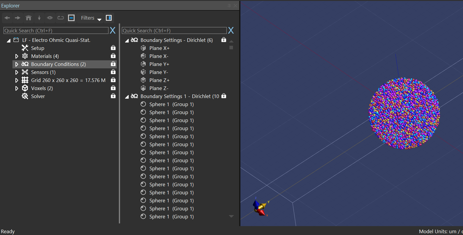
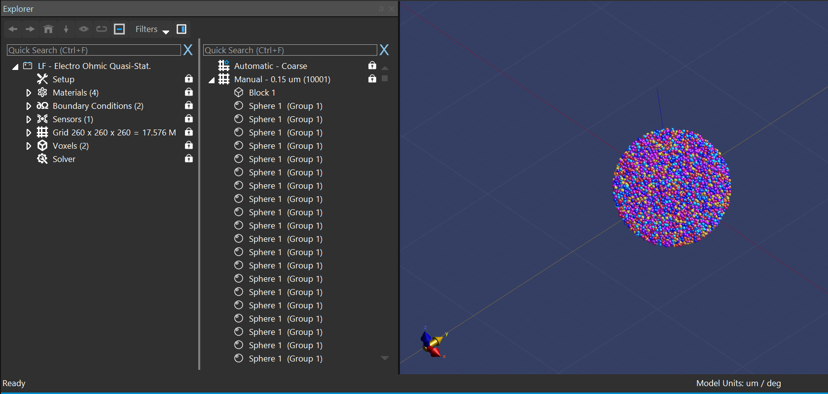
@ari I would suggest to check the voxels (View Voxels) since, after all, this is the only thing that the solver actually "sees". Maybe many of your spheres are actually not resolved at all?
Some slice views of the E and V fields could also be helpful, along with the actual potential values given in the boundary conditions. -
Additionally, check the Boundary Settings on the Outside (your first Boundary Settings). Seems you set the potential of the spheres to the same value as the outside boundary of your domain and that's why it's constant outside the spheres and at the domain walls as well (hard to make sense of the problem with the dimensions you mentioned and what's displayed in the plots). Also, when setting Voltage (Dirichlet) boundary conditions, make sure to set a 'reference' (Ground: 0V) voltage somewhere