Simulation Combiner Channel Parameters
-
Hello,
What voltage values should I input as the amplitudes under Analysis->Simulation Combiner->Channel Parameters if I want to visualize the E-field for a simulation with boundary settings set to a constant flux? Here are the pertinent details and what I've already tried.
I am performing an LF-electro ohmic quasi-static simulation with the rhesus macaque (Miss Able) model. I created two electrodes with cylinders to resemble the screw electrodes that we use for epidural ACS in my lab.
Under the Simulation->Boundary Conditions->Boundary Settings for the two electrodes, I set the Boundary Type to Flux, with a constant flux of 2.47 mA. Then, I checked the Treat as Port box.
I understand that the voltages for the amplitudes under Analysis->Simulation Combiner->Channel Parameters applies to the analysis, so it did not change the constant flux value that I input for the simulation stage. However, I don't know what voltages I should input to reflect the true E-field value for the 2.47 mA.
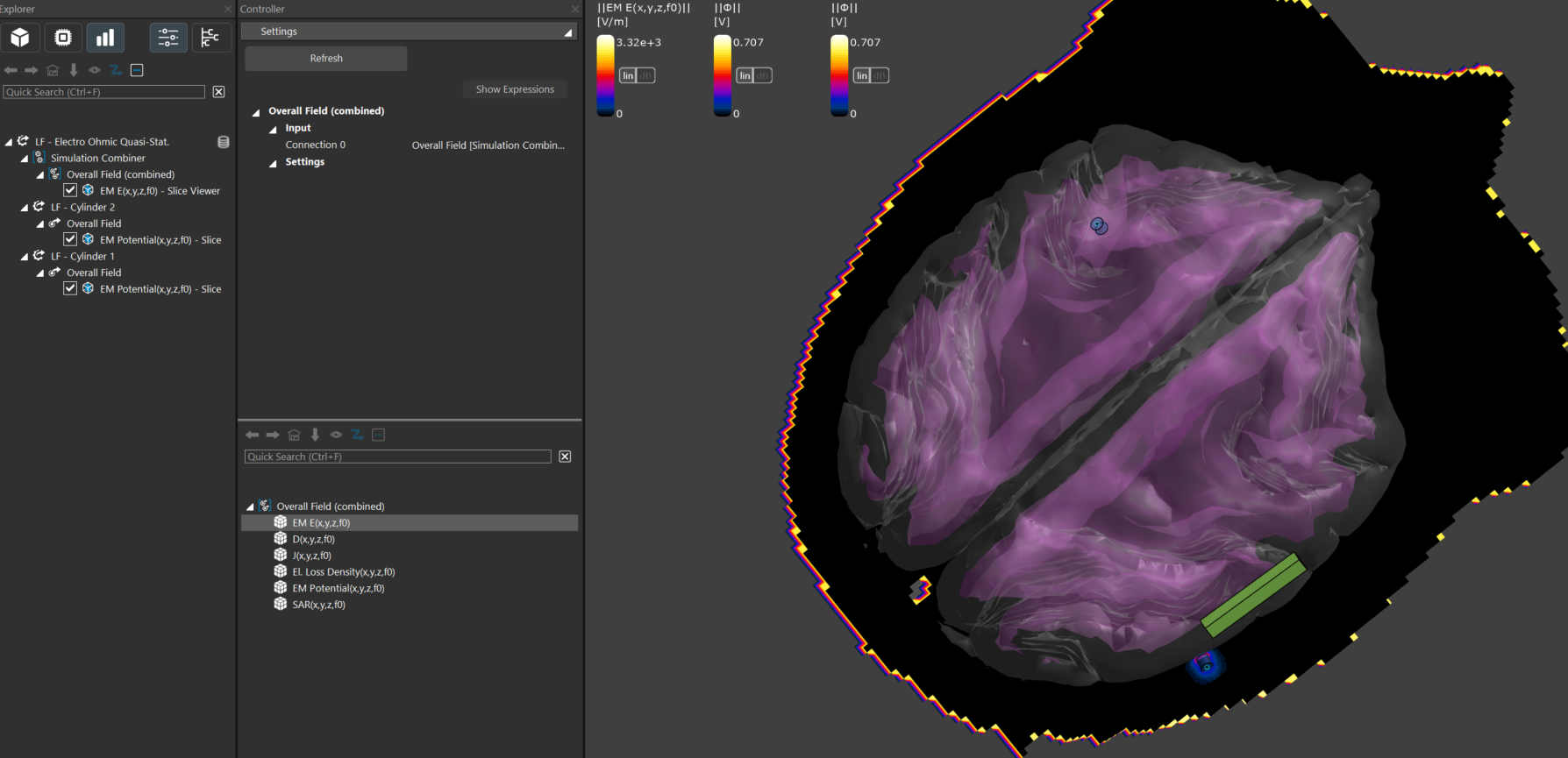
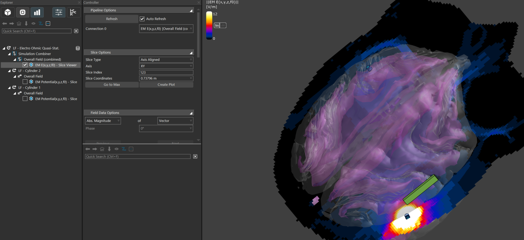
I tried acquiring the appropriate voltages for the simulation combiner amplitudes by outputting the EM potential for each of the electrodes. This yielded a max of 0.707 V. Then, I input that value into the simulation combiner amplitudes field, setting amplitude 1 to 0.707 V and amplitude 2 to -0.707 V. Next, I clicked on EM Sensor Combiner for the overall field, EM E, and Slice Viewer. However, when I tried following these same steps for a constant flux of 1.98 mA, it also exhibited 0.707 V.
So, either I'm doing something wrong or I do not understand the parameters that I am using to visualize the E-field properly. I was also wondering if perhaps the electric field was normalized for the simulation combiner, so it is not giving me the true E-field value for a given constant flux. Could you please help me output the accurate E-field value for ACS, given a constant flux of some value (in milliamps)?
Thanks,
Ian
-
If I understand correctly, you would like to have one simulation with a total current of 2.47mA and another one with 1.98mA.
Sim4Life EQS solvers use Dirichlet boundary conditions for the electrodes (fixed voltage) as they solve for electric potential and electrode surfaces are assumed to be equipotential, hence the flux should be able to vary to ensure an equipotential surface.
Moreover, when you check “Treat as port” for the LF solvers, you should be able to see in the log that they run 1 simulation per port, by setting this port to 1V and all the rest to 0V.
With only 2 electrodes, and assuming you have one anode and one cathode, I would suggest the following:
- Assign Dirichlet boundary conditions to the electrodes (one setting per electrode, for instance 0.5V and -0.5V).
- Run the simulation
- Extract the total current of the simulation (select the "Overall Field" and use the "Current Extractor" from the ribbon).
- Normalize your fields of interest by the scaling factor: desired current/total current.
- Visualize the output of your normalized field.
I hope this helps!
Hello! It looks like you're interested in this conversation, but you don't have an account yet.
Getting fed up of having to scroll through the same posts each visit? When you register for an account, you'll always come back to exactly where you were before, and choose to be notified of new replies (either via email, or push notification). You'll also be able to save bookmarks and upvote posts to show your appreciation to other community members.
With your input, this post could be even better 💗
Register Login