Normalization for precise current control via Jupyter
-
I would like to use the normalization feature with EMLF Overall Field sensor to precisely control the current output by electrodes, in such a way that it emulates the function of a constant current controlled stimulator like a Digitimer DS5. I have managed to do this using a very simple example with a cylinder, a plane bisecting the cylinder, with electrodes placed on either end of the cylinder. The results I see via a flux evaluator are exactly what I set with the normalization settings.
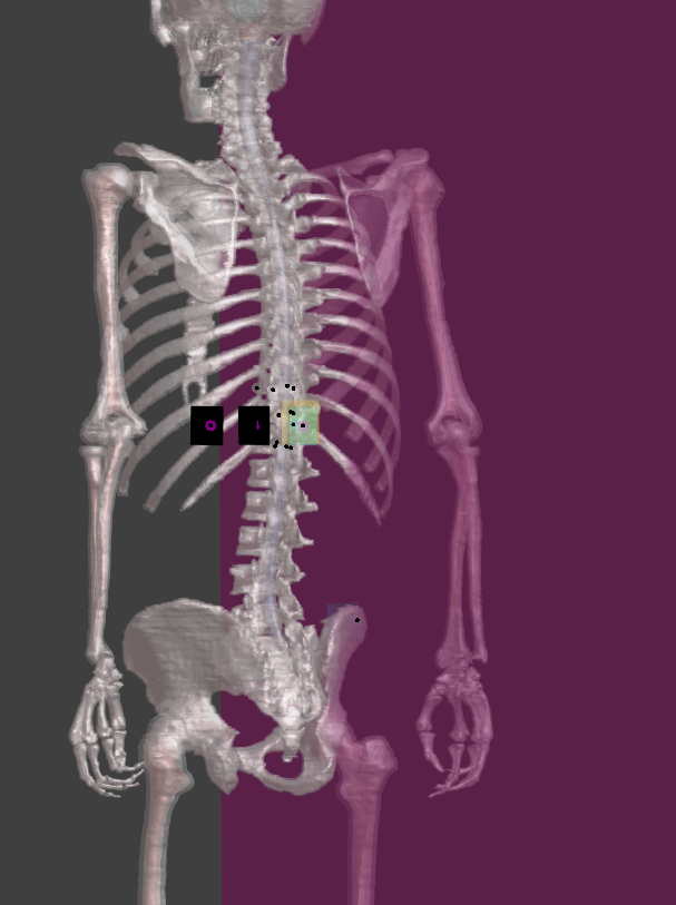
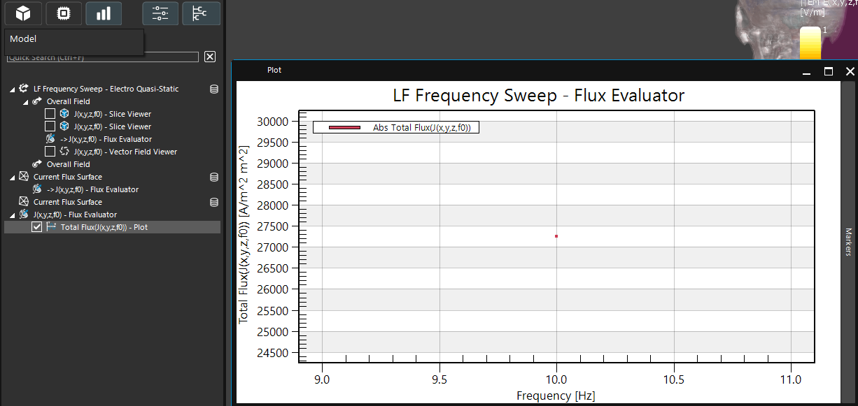
Attempting this with electrodes placed on the Jeduk model is giving unclear results. I have the positive electrode placed near T10 and the negative placed at the iliac crest, with voltages set to +/- 75 volts respectively. After running simulation, I normalize the current through the iso surface to 10mA. I am unable to select the reference surface. I have a surface in the XZ plane in between the two electrodes. The magnitude of the total current is displayed as 27253 amps with the flux evaluator. This seems like it is due to improper normalization, as I cannot select or even see which iso surface is being selected.
How do I set the iso-surface used as reference for the normalization, such that I can precisely control the current passing through the electrodes? Is there another method for achieving precise current control that is realizable via Jupyter scripting?(I understand that I should set the surface for the flux evaluator such that it is adjacent to the surface of the electrode, but the iso surface reference for normalization still does not correspond to this)


-
If I understand correctly, you want to extract the total current of your simulation and then use this value to normalize your resulting fields.
To do this in the GUI:
1- You should select "Overall Field"
2- In the ribbon, go to "Field Data Tools" and click on "Current Extractor". This will compute the "Total Flux" from your simulation.
3- You can then use this computed value to scale your field of interest. Select the field and in "Field Data Tools" click on the "Multiplier". The scaling factor should be your desired total current divided by the actual current value computed previously. -
Hi @carbonell, I understand how to do to process you described, and it works well for simple cases where one measures the current across a simple surface or shape. My issue is, "Current Extractor' measures this current in reference to an iso-surface, which is chosen by default and does not seem to be user-selectable. This means that the current measured is completely inaccurate when measuring the current flowing through a human model between a cathode/anode pair.
I would like to know how to choose this iso-surface, such that it could measure the current flowing across the electrode-skin interface, or in a closed loop between two electrodes, simulating the function of a constant current stimulator like a Digitimer DS5. I am running an EMLF simulation feeding into a NEURON simulation, but precise control of current for what should be a relatively straightforward setup has proven quite challenging to do consistently. -
Dear @cbenj33
The automatic flux integrator (“Current Extractor”) works when it is possible to clearly separate an anode and a cathode. It is not suitable for cases with multiple sources.The reason is that the software chooses the isosurface for the numerical surface integral of the current density J as the surface where the potential equals the average between the two Dirichlet (voltage) boundary conditions. This default choice ensures that the surface is not too close to the electrodes, where the E- and J-field gradients are high, and where small discretization errors could lead to large uncertainties in the integrated flux.
However, there is an option to adjust the isosurface to a different percentage of the potential difference. This setting—“Iso surface level as percentage of the potential difference”—lets you move the surface closer to one electrode (e.g., 10%) or the other (e.g., 90%). A value of 50% corresponds to the default midpoint. I do not recommend placing the surface too close to the electrodes for the reasons explained above.

The “Surface refinement” option allows you to increase the discretization density on the surface. You can perform a convergence analysis by refining the surface until the extracted current changes by only a few percent or less.
That said, the user can also perform this operation manually. You can create any closed surface that encloses one electrode—or that divides the computational domain into two parts, each containing either the anode or the cathode—and use this surface to interpolate the J-field. After interpolation, the software provides the option to calculate the flux.
I assume you are using the LF Ohmic Current dominated solver. Since you know the voltage applied between the contacts and the current through the electrode for that voltage, you can simply apply Ohm’s law to determine the voltage needed for a desired current. Alternatively, you can use the “Multiplier” function in the Field Data Tools to scale the E- or E-potential field to the desired current by applying the factor:
scaling factor = I_desired/I_measured
In my EM–neuronal coupled simulations, I usually use the multiplier method and link the neuronal simulation via the Analysis/Cache option in the source settings, selecting the multiplier applied to the E-potential.
I hope this clears up your doubts.
All the best!
-
Hi @AntoninoMC, I really appreciate this answer as it helped clear some things up for me. I understand the current extractor much better than I did before and I've realized why I may have been running into some issues.
The method of using the analysis as a source also seems to be preferable. I am using the EMLF Electro Quasi-Static model for modelling transcutaneous spinal cord stim, for which precise control of the current is of absolute importance. The multiplier method seems to be the way to go for feeding into the NEURON simulation, as it means I don't have to rerun my EMLF sim.
One thing I'm wondering, when I select the analysis/cache as a source, I lose the ability to use the contact impedance model in the NEURON setup. If I use a contact impedance model producer to modulate the resulting EM field from the multiplier, I lose the ability to set pulse parameters, which then seems to prevent NEURON from running a simulation. Do you know if there's a way to use the analysis connection with a multiplier AND a contact impedance model simultaneously for driving a NEURON simulation? -
 A AntoninoMC referenced this topic on