How do grid settings work?
-
-
An optimum grid setting should be one which provides good representation of the physical geometry with minimum requirement on grid resolution (does not require extremely small grid step), so it is always a trade off. I would suggest that you use different grid step and simulation period, until you get a set of results which do not vary anymore with changing grid step and period, then you will be more confident of the simulation result since they appear to be invariant with respect to simulation set up.
-
It is important to check voxels (the discretized model) before running the simulation.
-
You may improve grid resolution further on significant parts of your structure. I suggest you to use “connectivity check" tool under simulation once you generate voxel. It will give warning when there are floating sources and/or sensors. You can try this tool with your original setup and my setup.
-
For an FDTD simulation, the most important thing is that you get a correct voxelized model to simulate, if the voxels are wrong (do not represent the actual device) then all the simulation results will be wrong. I strongly suggest you to go through the user manual for voxeling and gridline tips, it will be of great help for your simulation tasks.
-
The gridder works in the following way:
- Model objects placed inside grid settings folders acquire grid baselines (shown in red)
- The Resolution parameter controls how close baselines can be from each other. If two baselines are closer to each other than the Resolution, one of the two baselines is removed.
- The space between baselines is filled with grid lines (shown in white) such that the grid cells are smaller than the Max Step parameter and smaller than a fraction (typically 1/14) of the wavelength.
- Since there is (ultimately) only one grid but there may be several grid setting folders, some parameters can conflict with each others. The Priority setting determines which setting folder takes precedence for the placement of baselines.
-
To obtain a "uniform" grid, set the Priority to 0, such that no baselines are created.
-
-
-
An optimum grid setting should be one which provides good representation of the physical geometry with minimum requirement on grid resolution (does not require extremely small grid step), so it is always a trade off. I would suggest that you use different grid step and simulation period, until you get a set of results which do not vary anymore with changing grid step and period, then you will be more confident of the simulation result since they appear to be invariant with respect to simulation set up.
-
It is important to check voxels (the discretized model) before running the simulation.
-
You may improve grid resolution further on significant parts of your structure. I suggest you to use “connectivity check" tool under simulation once you generate voxel. It will give warning when there are floating sources and/or sensors. You can try this tool with your original setup and my setup.
-
For an FDTD simulation, the most important thing is that you get a correct voxelized model to simulate, if the voxels are wrong (do not represent the actual device) then all the simulation results will be wrong. I strongly suggest you to go through the user manual for voxeling and gridline tips, it will be of great help for your simulation tasks.
-
The gridder works in the following way:
- Model objects placed inside grid settings folders acquire grid baselines (shown in red)
- The Resolution parameter controls how close baselines can be from each other. If two baselines are closer to each other than the Resolution, one of the two baselines is removed.
- The space between baselines is filled with grid lines (shown in white) such that the grid cells are smaller than the Max Step parameter and smaller than a fraction (typically 1/14) of the wavelength.
- Since there is (ultimately) only one grid but there may be several grid setting folders, some parameters can conflict with each others. The Priority setting determines which setting folder takes precedence for the placement of baselines.
-
To obtain a "uniform" grid, set the Priority to 0, such that no baselines are created.
Hi
I'm trying to obtain a cubic uniform grid. I set the grid priorities to 0, and all the Maximum Steps and the Geometry Resolutions to be the same. But yet, in Options\Main Grid\Min Step and Max Step are not equals for all the axes.
How can we obtain a cubic uniform grid?Thank you,
Oshrit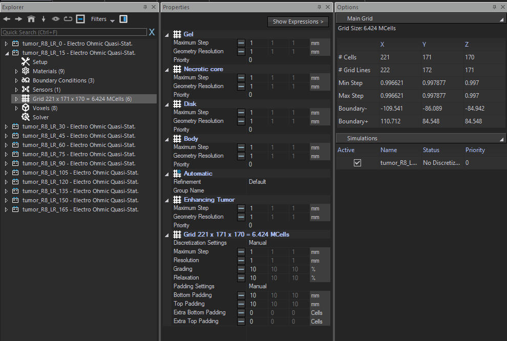
-
-
to get a uniform grid, you need
Geometry Resolution = 0(meaning no constraint on the grid coming from the CAD objects), andPriority = 100meaning this setting always has precedence over the other ones.
You might also need to delete the other settings (or, equivalently, move all the objects inside this "Uniform" grid setting). -
@farhana said in How do grid settings work?:
What is the relation between grid step and simulation period?
there is not really any relation. One is the about the distance between 2 grid lines, the other is the duration of the simulation (in physical units, not the time it will take for the simulation to run).
However, the time step is determined by the size of the smallest grid cell (a stability requirement of the FDTD method) and the number of time steps needed is determined by the size and number of simulation periods. So effectively, the total runtime depends simultaneously (and linearly) on both the grid step and the number of simulation periods.
-
D dbsim4 referenced this topic on
-
D dbsim4 referenced this topic on