Skip to content
  • Search
Skins
  • Light
  • Cerulean
  • Cosmo
  • Flatly
  • Journal
  • Litera
  • Lumen
  • Lux
  • Materia
  • Minty
  • Morph
  • Pulse
  • Sandstone
  • Simplex
  • Sketchy
  • Spacelab
  • United
  • Yeti
  • Zephyr
  • Dark
  • Cyborg
  • Darkly
  • Quartz
  • Slate
  • Solar
  • Superhero
  • Vapor

  • Default (No Skin)
  • No Skin
Collapse

ZMT zurich med tech

  1. Home
  2. Sim4Life
  3. Simulations & Solvers
  4. stimulation

stimulation

Scheduled Pinned Locked Moved Unsolved Simulations & Solvers
5 Posts 2 Posters 447 Views
  • Oldest to Newest
  • Newest to Oldest
  • Most Votes
Reply
  • Reply as topic
Log in to reply
This topic has been deleted. Only users with topic management privileges can see it.
  • H Offline
    H Offline
    hiTina
    wrote on 7 Oct 2021, 04:10 last edited by
    #1

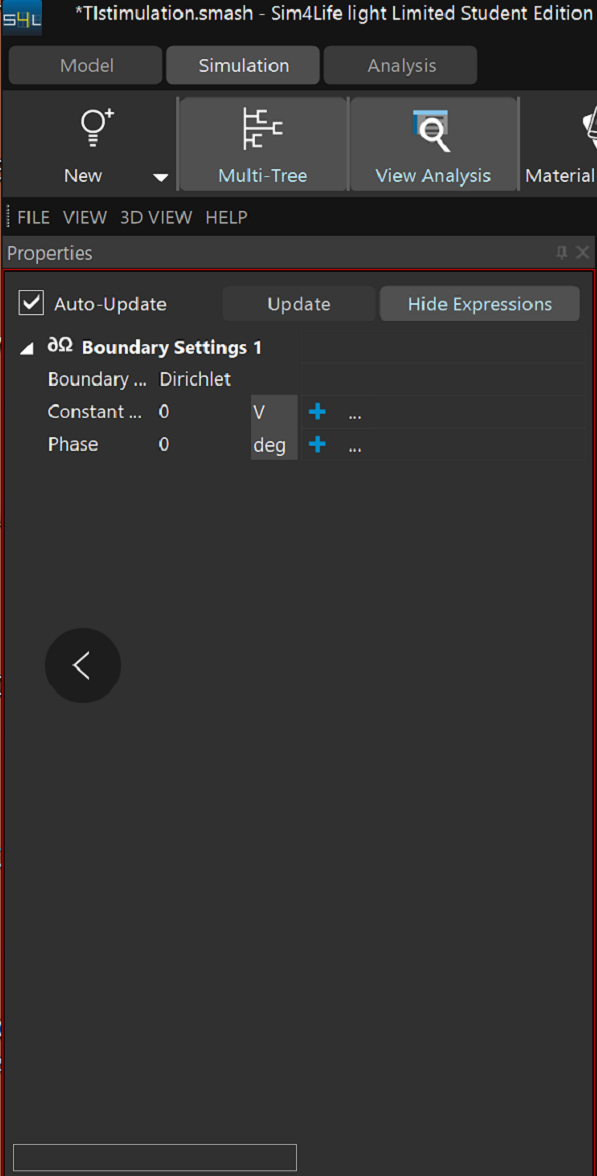
    I perform tDCS, but I have some problems.I am using the Electro Quasi-static LF solver, I set the electrode as the simulation boundary conditions where I can input the voltage and flux.Is there a way to input the desired current amplitude somewhere ?
    ![alt text]微信图片_20211007120849.png
    best wishes

    1 Reply Last reply
    0
    • G Offline
      G Offline
      gbgbha
      wrote on 7 Oct 2021, 16:31 last edited by
      #2

      Hi @hiTina, I think you can find your answer in the following thread: https://forum.zmt.swiss/topic/121/lf-magneto-static-vector-potential-solver
      The flux boundary condition is not suitable here. You should use voltage boundary condition (Dirichlet) and then scale up or down to get the desired current.

      H 1 Reply Last reply 8 Oct 2021, 08:10
      0
      • G gbgbha
        7 Oct 2021, 16:31

        Hi @hiTina, I think you can find your answer in the following thread: https://forum.zmt.swiss/topic/121/lf-magneto-static-vector-potential-solver
        The flux boundary condition is not suitable here. You should use voltage boundary condition (Dirichlet) and then scale up or down to get the desired current.

        H Offline
        H Offline
        hiTina
        wrote on 8 Oct 2021, 08:10 last edited by
        #3

        @gbgbha thanks for your reply.I have considered your suggestion.I also have some confused problem. so Is it correct that I set the stimulation electrode as the boundary condition? or should I set the electrode as PEC? I plan to perform TACS stimulation.

        1 Reply Last reply
        0
        • G Offline
          G Offline
          gbgbha
          wrote on 13 Oct 2021, 17:10 last edited by
          #4

          @hiTina yes you should use the Dirichlet boundary condition at the two electrodes, and no you should not set them as PEC, because EM LF solvers do not accept the same object in both the material setting and the boundary condition setting.

          H 1 Reply Last reply 18 Oct 2021, 03:58
          0
          • G gbgbha
            13 Oct 2021, 17:10

            @hiTina yes you should use the Dirichlet boundary condition at the two electrodes, and no you should not set them as PEC, because EM LF solvers do not accept the same object in both the material setting and the boundary condition setting.

            H Offline
            H Offline
            hiTina
            wrote on 18 Oct 2021, 03:58 last edited by
            #5

            @gbgbha you are right.thanks you very much.

            1 Reply Last reply
            0
            Reply
            • Reply as topic
            Log in to reply
            • Oldest to Newest
            • Newest to Oldest
            • Most Votes

            2/5

            7 Oct 2021, 16:31


            • Login

            • Don't have an account? Register

            • Login or register to search.
            2 out of 5
            • First post
              2/5
              Last post
            0
            • Search