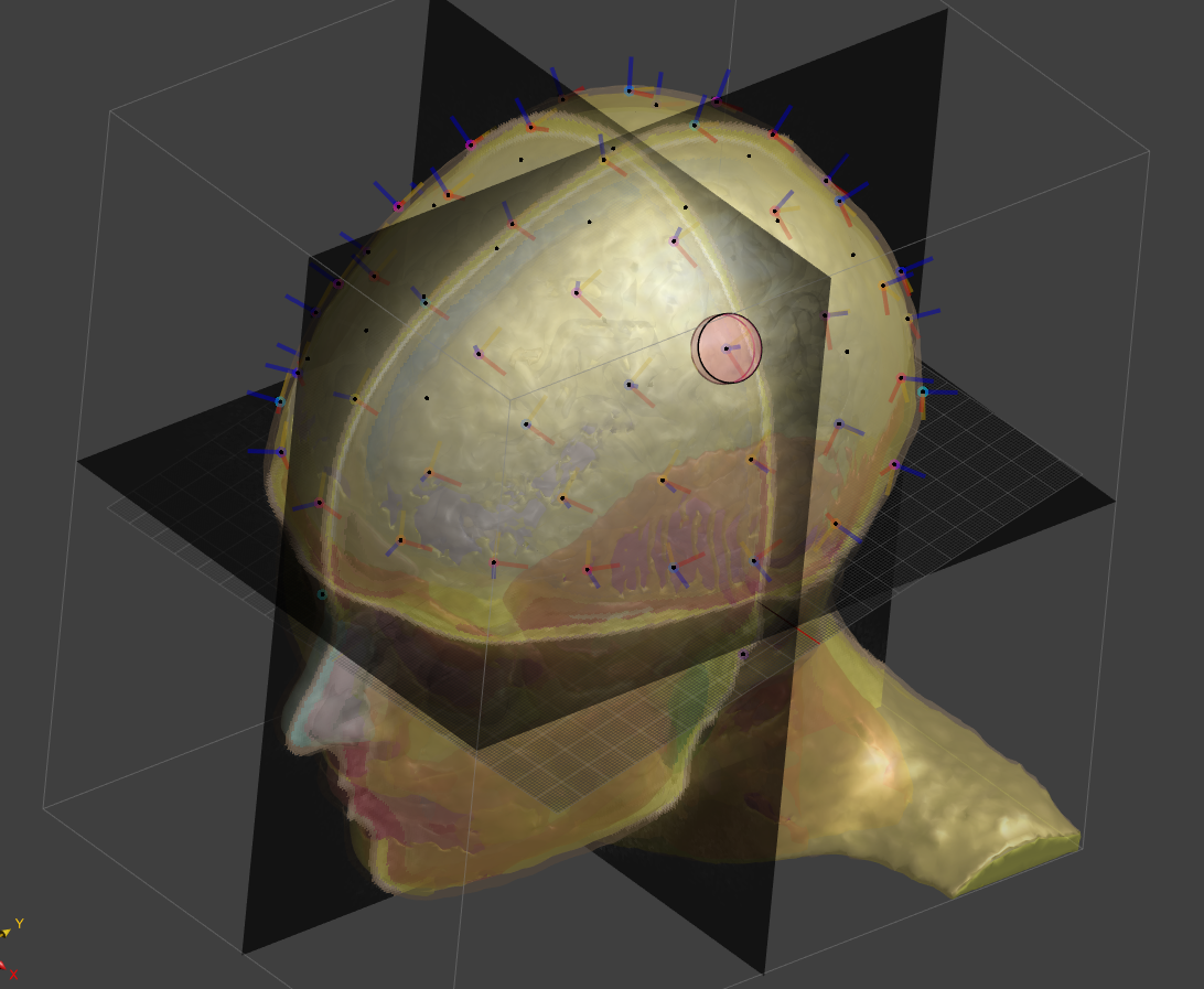
Automatic Head Model including 1010-System / Electrode Placement
-
I tried to repeat what the script is doing here:
Youtube VideoTo predict the 4 landmarks:
- Select the MRI (T1-weighted image)
- Select the Head-Modeling -> Auto-Label tool
- Under Inference Task choose the 10-10-system landmarks, press Run button
You then
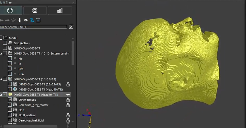
- segment the head (choose the Head40 "Inference Task" in the Auto-Label tool)
- extract surfaces from the labelfield,
- select the skin and the landmarks
- run the Head Modeling -> 10-10 System tool: this creates the local coordinate system points for each 10-10 system point
- select your template electrode and the 10-10 system points
- run the Head Modeling -> Electrode Placement tool
-
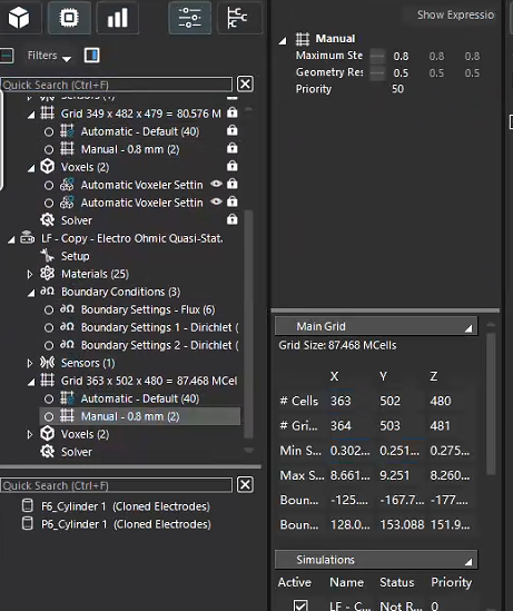
@bryn Thank you very much for your help. I successfully completed the TI simulation, but I found that the simulation results for the two single-electrode pairs are not completely symmetrical. The maximum electric fields they generate in the GM are 0.0933 V/m and 0.0882 V/m, respectively. My method was to clone the two LF-Electro Ohmic Quasi-Stat simulations, modifying the frequency and boundary conditions for each. The electrode pairs I chose are F5-P5 and F6-P6. Is my approach correct, or should I consider using a multi-port simulation instead?
-
Hi @lucky_lin Did you update the grid before running the first simulation? And did you make any changes to the model after setting the grid for the first simulation?
If possible, please share your project with us at s4l-support@zmt.swiss, and we will take a look. -
-
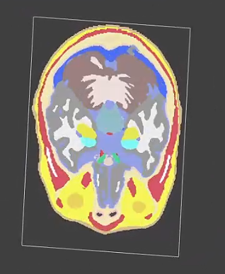
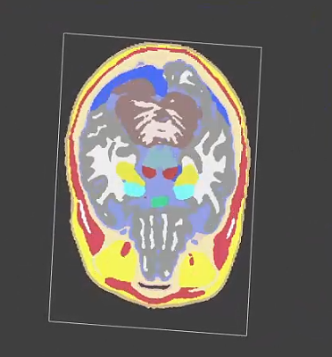
Did you check the segmentation? Is the head symmetric? Are there differences between left/right, e.g. thinner skull, holes in the CSF or Dura, etc.
If there are holes, and these seem to be the cause of the asymmetry, maybe reduce the
output_spacingto the default 0.3mm. The valueoutput_spacing=0.6set above in the script could be too coarse to resolve certain thin tissues.Do the the electrodes seem symmetrically placed wrt the anatomy?
Did you check the simulation voxels? Is there something "asymmetric" about the voxels?
-
@lucky_lin "Other tissues" is basically fat. I don't think this is an issue.
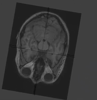
Note, that the head is not perfectly aligned with the axis, i.e. your XY plane may not be perpendicular to the "up" direction. You can also change the slice by using the interactive slice instead of axis-aligned.
Finally. Yes, it is normal that real subjects/people have asymmetrical features. If you are interested in the research question, you could test the impact of individual tissues (conductivity) by
- assigning the same tissue property to all tissues (except for Air?). Is this nearly/more symmetrical?
- assigning the same tissue property to all tissues, except for one tissue (and Air). Candidates are the thin layers around the brain, e.g. Dura, CSF, Brain grey matter, Skull cortical/cancellous, [Galea, Muscle, ...].
-
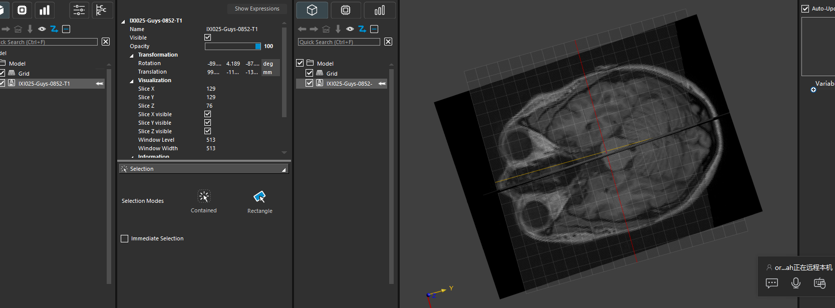
@bryn I tried to set both the rotation and translation of T1W to 0 and then generate the reference point, but it reported an error: Modeler : [Error] Exception during import: Expecting 'Version 1.0' on first line Modeler : [Error] operation unsuccessful.
-
The T1w image is placed in world (scanner) coordinates. This is useful, e.g. to align different acquisitions (e.g. T1, T2 with different resolutions or field of view).
You could remove the rotation and translation, e.g., by setting an identity transform. However, in my experience, it is often useful to preserve the position in world coordinates.
img = XCoreModeling.Import("some_t1w_mri.nii.gz") img.Transform = XCoreModeling.Transform() -
I don't understand what you are doing. The error looks like Sim4Life cannot parse the .pts file produced by the landmark predictor.
- did you edit the .pts file manually?
- where/how did you set the rotation/translation to "0"?
- did you try to set the transform [to zero] (before running the prediction) as suggested in my last post?
-
-
I can reproduce your issue. If I set the transform to "0", i.e. Identity, the predictor fails. The head40 segmentation is also less accurate! We need to investigate.
A workaround would be:
- load image
- predict landmarks & segmentation
- compute inverse image transform
- apply this inverse to landmarks/segmentation/surfaces/etc
# assumes verts and labelfield are already predicted (without setting transform to "0") inv_tx = img.Transform.Inverse() # transform segmentation labelfield.ApplyTransform(inv_tx ) # transform landmarks for v in verts: v.ApplyTransform(inv_tx ) -
The issue is that our neural network was trained with the data in the RAS orientation (with some deviation +- 15 degrees, and flipping in all axes). If you manually edit the transform, you break assumptions used to pre-orient the data into RAS ordering.
Since RAS is a widely used convention in neuroscience, and medical images are always acquired with a direction (rotation) matrix and offset (translation), I think it is best you don't modify the transform.
For instance, if you try to assign DTI-based conductivity maps - you will need to rotate the grid AND the tensors accordingly. It can be done, but it will be more effort...
If this is to investigate if the fields are (nearly) symmetric, I suggest you
- find an approximate symmetry plane (wrt to the brain or skull or ...)
- align the plane of a slice viewer perpendicular to the symmetry plane
Hello! It looks like you're interested in this conversation, but you don't have an account yet.
Getting fed up of having to scroll through the same posts each visit? When you register for an account, you'll always come back to exactly where you were before, and choose to be notified of new replies (either via email, or push notification). You'll also be able to save bookmarks and upvote posts to show your appreciation to other community members.
With your input, this post could be even better 💗
Register Login