Different frequencies in electrodes
-
I want to perform TACS (Trans-cranial Alternating Current Stimulation) with 2 electrode pairs, each at a slightly different frequency to create an envelope of the difference. I can not find something like that. The only thing that is possible is to use Electro Quasi-static LF Solver and have one frequency set.
Do you know how can I achieve this?
Thanks!
-
Hello dstoupis,
I believe you aim to model the so-called temporal interference. The is a tool in Sim4Life for this called Max Modulation. You need two simulation with the same grid. Then you can multi-select the two fields in the Output View (each from one simulation) to have the Max Modulation button appear in the Ribbon.
Best,
Habib -
Hello dstoupis,
I believe you aim to model the so-called temporal interference. The is a tool in Sim4Life for this called Max Modulation. You need two simulation with the same grid. Then you can multi-select the two fields in the Output View (each from one simulation) to have the Max Modulation button appear in the Ribbon.
Best,
Habib@Habib said in Different frequencies in electrodes:
Hello dstoupis,
I believe you aim to model the so-called temporal interference. The is a tool in Sim4Life for this called Max Modulation. You need two simulation with the same grid. Then you can multi-select the two fields in the Output View (each from one simulation) to have the Max Modulation button appear in the Ribbon.
Best,
HabibThank you @Habib!
It was a simple selection of the two "Overall Fields" to have the "Max Modulation" tool show up! It helps a lot, since extracting the data and the processing it using Python to superimpose the fields and get the corresponding graphs, takes a lot of time.For future reference:
- Create two LF Electro Quasi-Static simulations one with the first desired frequency and another with the second desired frequency
- Use the same grid for the simulations (Grid point count must be the same)
- Run the simulations and extract the sensors
- Select the extracted sensors and magically the Max Modulation tool will appear
-
@Habib said in Different frequencies in electrodes:
Hello dstoupis,
I believe you aim to model the so-called temporal interference. The is a tool in Sim4Life for this called Max Modulation. You need two simulation with the same grid. Then you can multi-select the two fields in the Output View (each from one simulation) to have the Max Modulation button appear in the Ribbon.
Best,
HabibThank you @Habib!
It was a simple selection of the two "Overall Fields" to have the "Max Modulation" tool show up! It helps a lot, since extracting the data and the processing it using Python to superimpose the fields and get the corresponding graphs, takes a lot of time.For future reference:
- Create two LF Electro Quasi-Static simulations one with the first desired frequency and another with the second desired frequency
- Use the same grid for the simulations (Grid point count must be the same)
- Run the simulations and extract the sensors
- Select the extracted sensors and magically the Max Modulation tool will appear
-
@dstoupis
also ,I have some questions when I perform the TDCS, when the max modulation appears, then what should I do to perform the next process? hope I can get your reply. -
@hitina
Please explain what you mean. Have you performed the tDCS analysis and generated the temporal interference field?@dstoupis Thanks for your reply.I have not generated the TI field.
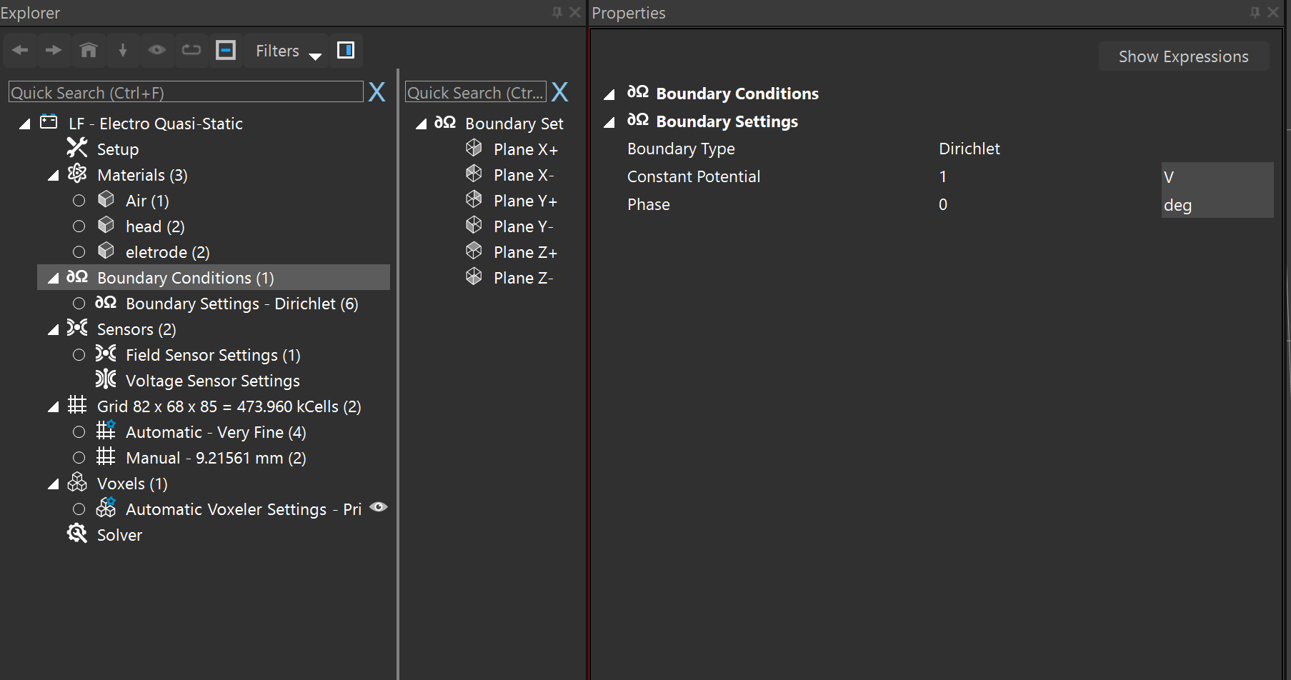
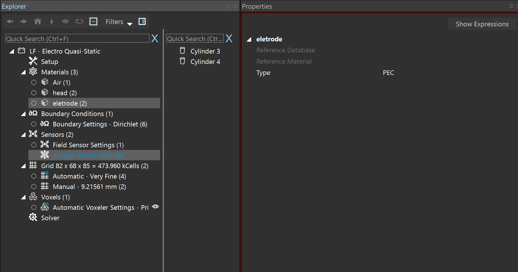
I have some confused questions. I choose the LF-electro Quasi- static as the solver. I want to know how can I set up the boundary conditons .! what's more,as the picture shows,how to set up the the current and the voltage of the eletrode.
I am learning the performance of transcranial temporal interference stimulation in this days.
hope your reply.
best wishes. -
@hitina
Please explain what you mean. Have you performed the tDCS analysis and generated the temporal interference field? -
@hitina
Please explain what you mean. Have you performed the tDCS analysis and generated the temporal interference field? -
This post is deleted!
-
Hello dstoupis,
I believe you aim to model the so-called temporal interference. The is a tool in Sim4Life for this called Max Modulation. You need two simulation with the same grid. Then you can multi-select the two fields in the Output View (each from one simulation) to have the Max Modulation button appear in the Ribbon.
Best,
Habib@habib hello
i am performing TI simulation with sim4life and after using the max modulation to see the interference between the two field. I have electric field spreading all arround the mesh not only in the brain but in different part or the model (MIDA fULL aNISOTROPY MODEL).
And if i want to know which configuration of the electrode is better for TI simulation, should i compare the amount of electric field that reach the targeted region( for example in the hippocampus)? -
@habib hello
i am performing TI simulation with sim4life and after using the max modulation to see the interference between the two field. I have electric field spreading all arround the mesh not only in the brain but in different part or the model (MIDA fULL aNISOTROPY MODEL).
And if i want to know which configuration of the electrode is better for TI simulation, should i compare the amount of electric field that reach the targeted region( for example in the hippocampus)?