no temperature increasing was observed when using the PWM sine waveform with 10% duty cycle

-
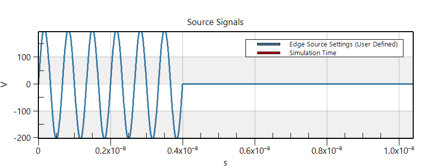
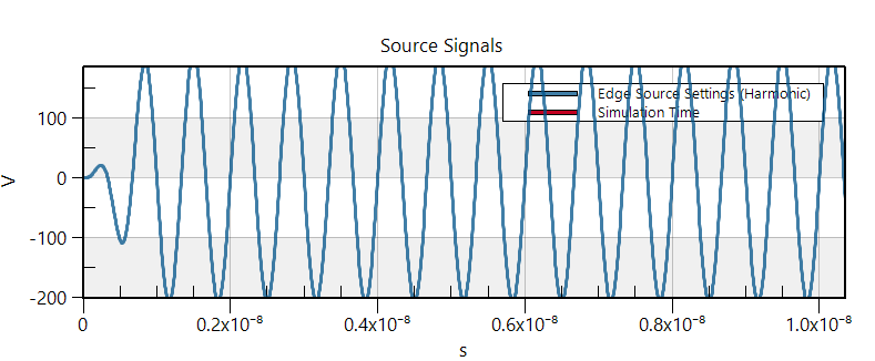
I want use the EM FDTD and the Thermal Transient modules to simulate the heating problem. Firstly, I used the sine waveform as the excitation signal. The microwave induced heat caused significant temperature increasing. However, when I replaced the continuous sine waveform into the waveform with pulse width modulation (the duty cycle is 10%), it doesn't see temperature increasing any more. I noticed that I didn't select the option of normalization in the source of Thermal Transient. I don't knwo whether I should select the normalization and set the scale factor as 1 W? The normal sine waveform and the modulated sine waveform are shown in below, respectively.

-
Yes, you should select the normalization. If you don't, you do not control how much power goes into your thermal simulation. In your case, I suppose the power is extremely small (you should check that looking at the edge-source sensor of your EM simulation).
-
Yes, you should select the normalization. If you don't, you do not control how much power goes into your thermal simulation. In your case, I suppose the power is extremely small (you should check that looking at the edge-source sensor of your EM simulation).
@Sylvain Thank you for your reply. I have checked my simulation and found the input power is only 2.36e(-18) with the frequency of 0.15GHz. Although I have set the extracted frequency of 1.5 GHz, the s4l still only extracted the frequency of 0.15 GHz. I think this is reason why I cannot observe the temperature increasing in my simulation. And, I also found s4l cannot extracted the frequency which I have set in the simulation.
Actually, the amplitude of the sine wave with 10% duty cycle reaches 206 V, resulting in the input power larger than 1W. In this situation, how should I set the normalization factor of the power source. Could you please give me some suggestions?
-
Although I have set the extracted frequency of 1.5 GHz, the s4l still only extracted the frequency of 0.15 GHz
Please post some screenshots of your settings. Perhaps you are extracting more than one frequency and visualizing the wrong one.
Actually, the amplitude of the sine wave with 10% duty cycle reaches 206 V, resulting in the input power larger than 1W
How do you know that the power is larger than 1W? Where do you get that number?
Please also provide a screenshot of your thermal simulation settings, in particular the Source Settings
@Sylvain Thank you for your reply. Because the total impedance should be the antennas and voltage source impedance. Supposing the antennas impedance is 50 Ohm, the total impedance should be 100 Ohm since the impedance of the voltage source is 50 Ohm. Then, the power = U^2/R. In this simulation, the voltage is 206 V. Therefore, I think the power should be much larger than 1 W.
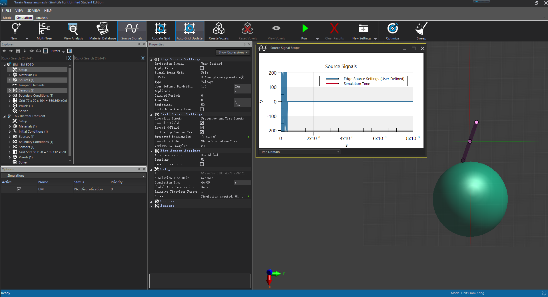
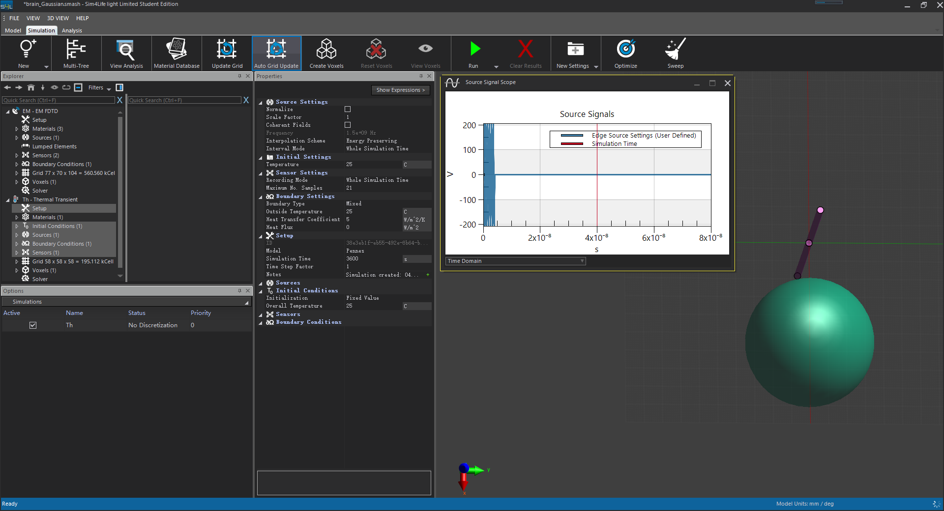
This EM and Thermal simulation settings for PWM sine wave with duty cycle of 10% as well as the computation results are shown in below.
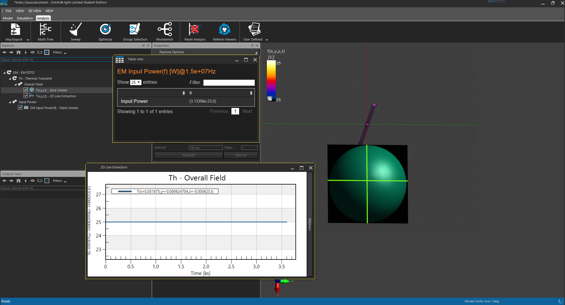
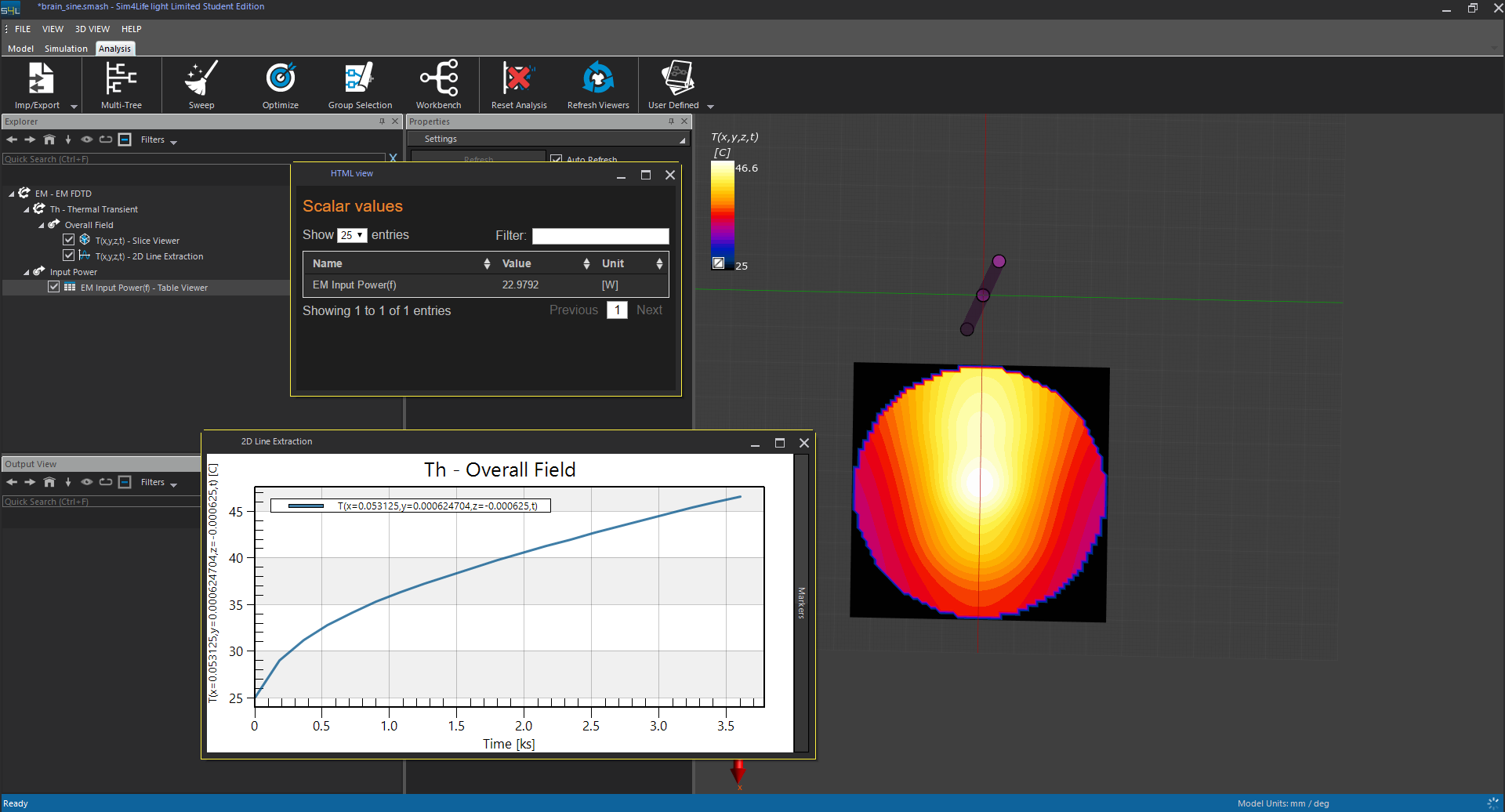
The results computed by using the normal continous sine is shown in below.
-
U is not the voltage across the resistor, nor the voltage across the ports of the source. It's the voltage of the generator inside the source (see power balance documentation). Thus U^2/R does not give you the input power. But I agree that in your case it seems the input power is around 23 W for your "sine" excitation and much smaller for your "Gaussian" excitation. I put those in quotes because I thought you were using the built-in Harmonic and Gaussian signals of Sim4Life, but you are using User-Defined signals.
I don't have much experience with those, because they are rarely needed. A duty-cycle of 10% can be very effectively simulated by scaling down the input power (using normalization) in the Thermal simulation by a factor of 10. -
U is not the voltage across the resistor, nor the voltage across the ports of the source. It's the voltage of the generator inside the source (see power balance documentation). Thus U^2/R does not give you the input power. But I agree that in your case it seems the input power is around 23 W for your "sine" excitation and much smaller for your "Gaussian" excitation. I put those in quotes because I thought you were using the built-in Harmonic and Gaussian signals of Sim4Life, but you are using User-Defined signals.
I don't have much experience with those, because they are rarely needed. A duty-cycle of 10% can be very effectively simulated by scaling down the input power (using normalization) in the Thermal simulation by a factor of 10.@Sylvain Thank you for your reply. I noticed that the s4l just extracted the frequency of 0.15GHz which is the not the main frequency of the PWM sine wave even though I have set the extraction frequency at 1.5GHz. Almost all of the input energy should be in the main frequency of the 1.5GHz. However, although I can adjust the bandwidth of the user difined excitation signal, the extracted frequency is always at 0.15GHz which cannot contain much energy. I guess this is the reason why the input energy is so small (3E-23 W), resulting in the no temperature increasing in the next thermal simulation. I think if we can change the EM input power, we will solve this problem.
-
I don't know what is going on in your case, there is either a mistake or a bug somewhere.
For the purpose of solving your problem, I would reiterate that you should use a plain simple Gaussian excitation with center frequency 1.5 GHz (and bandwidth 1.5 GHz) and use normalization to get the desired power into your thermal simulation. I would not recommend to use User-Defined excitation signals if all you need is to take into account the duty cycle. The timescale for temperature increase is much (!) larger than the timescale of your excitation. All that matters is the time-averaged deposited power. -
I don't know what is going on in your case, there is either a mistake or a bug somewhere.
For the purpose of solving your problem, I would reiterate that you should use a plain simple Gaussian excitation with center frequency 1.5 GHz (and bandwidth 1.5 GHz) and use normalization to get the desired power into your thermal simulation. I would not recommend to use User-Defined excitation signals if all you need is to take into account the duty cycle. The timescale for temperature increase is much (!) larger than the timescale of your excitation. All that matters is the time-averaged deposited power.@Sylvain I agree with you suggestion that the sine wave with duty cycle can be equal to the continuous sine wave as long as both of the excitation signals have the same time-averaged power. But, I still very curious about the computation algorithm of the s4l.
Hello! It looks like you're interested in this conversation, but you don't have an account yet.
Getting fed up of having to scroll through the same posts each visit? When you register for an account, you'll always come back to exactly where you were before, and choose to be notified of new replies (either via email, or push notification). You'll also be able to save bookmarks and upvote posts to show your appreciation to other community members.
With your input, this post could be even better 💗
Register Login