Compute the total current flowing between two electrodes in an Electro Quasistatic LF simulation

-
Hi @Sylvain, thanks for the tips. Is the total evaluated flux returned in RMS or absolute magnitude?
@gbgbha the evaluator would typically return a complex number, which should be interpreted as a phasor (at the frequency at which the fields were computed). Take the absolute value of that number to get the peak total current, divide by sqrt(2) to get the RMS.
-
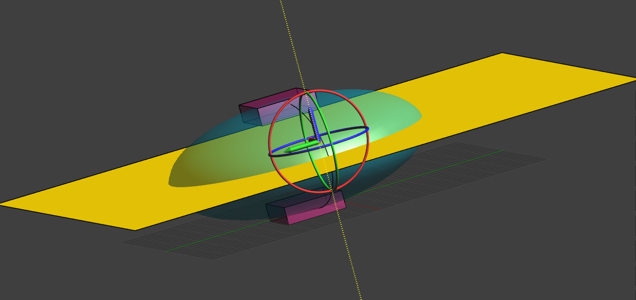
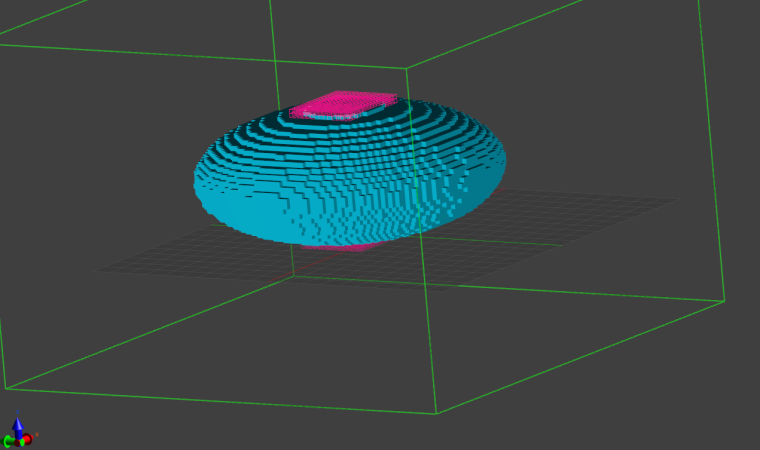
Assume we have an LF simulation with two electrodes, at + and - 1V, respectively, as shown in the voxel view below. We want to compute the total current flowing between the two electrodes.
We start by creating a plane that cut through the computational domain, with each electrode in either part of the plane:

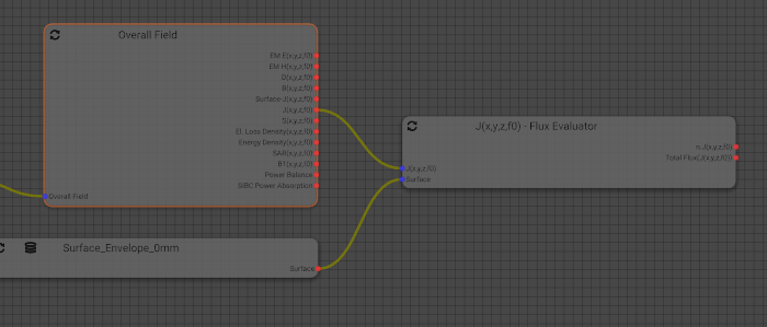
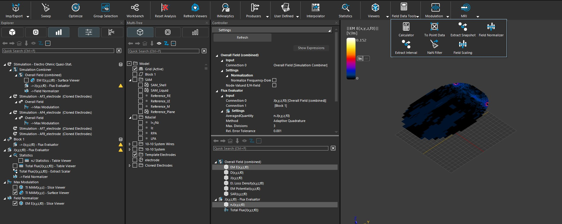
We then use the Flux Evaluator to compute the total current flowing through the plane:
-
@sylvain when we create the plane to compute the current ,I want to know how to set up the plane in the stimulation tab? setting in the boundary condition or else? hope your reply.
@hitina typically, you would create the plane in the Model tab of Sim4Life, then use it in the Analysis tab. Use the "Model-Tree" window to drag and drop the plane (or any other CAD object, for that matter) into the Explorer tree of the Analysis tab.
This creates a grid (Surface mesh) out of the CAD object that can be used for further postprocessing. Note that its mesh resolution can be changed (you would typically do that later, so you can see how it affects the end results when you refresh the pipeline).
By selecting the "Surface mesh" and any other field quantity (e.g. J(x,y,z,f0)), you can then make use of the "Flux Evaluator" algorithm. Use the Ctrl key to select multiple items.I hope this helps.
-
 S Sylvain referenced this topic on
-
@hitina typically, you would create the plane in the Model tab of Sim4Life, then use it in the Analysis tab. Use the "Model-Tree" window to drag and drop the plane (or any other CAD object, for that matter) into the Explorer tree of the Analysis tab.
This creates a grid (Surface mesh) out of the CAD object that can be used for further postprocessing. Note that its mesh resolution can be changed (you would typically do that later, so you can see how it affects the end results when you refresh the pipeline).
By selecting the "Surface mesh" and any other field quantity (e.g. J(x,y,z,f0)), you can then make use of the "Flux Evaluator" algorithm. Use the Ctrl key to select multiple items.I hope this helps.
@sylvain Thanks for your reply. I try to create a plane and drag and drop the plane into the Explorer tree of the Analysis tab.I enable the J(x,y,z,f0) and click the Flux Evaluator button. The result shows errors as follow.

How can I use the created plane to compute the current?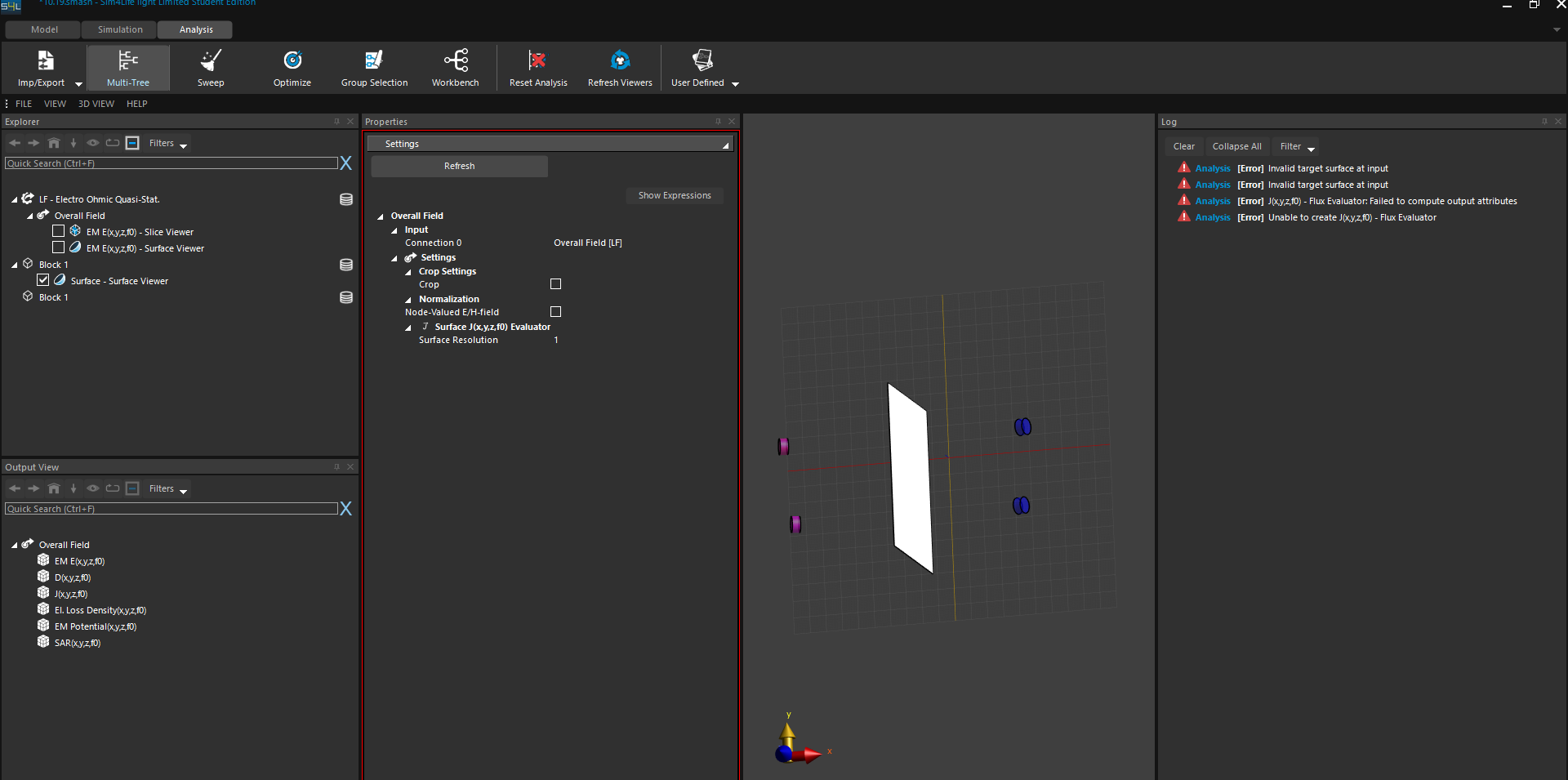
Should I set the created plane as the target surface of the flux evaluator ? the error shows invalid target surface at input. looking forward to your reply. -
@sylvain Thanks for your reply. I try to create a plane and drag and drop the plane into the Explorer tree of the Analysis tab.I enable the J(x,y,z,f0) and click the Flux Evaluator button. The result shows errors as follow.
How can I use the created plane to compute the current?
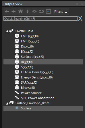
Should I set the created plane as the target surface of the flux evaluator ? the error shows invalid target surface at input. looking forward to your reply.@hiTina it's not clear from your post whether you selected both the J field and the surface before clicking "Flux Evaluator".
What I mean is that you should see something like this in theOutput Viewand then click "Flux Evaluator"
Once you've done that, the
Workbenchwould show something like this:
-
@hiTina it's not clear from your post whether you selected both the J field and the surface before clicking "Flux Evaluator".
What I mean is that you should see something like this in theOutput Viewand then click "Flux Evaluator"
Once you've done that, the
Workbenchwould show something like this:
-
O oeddaoui referenced this topic on
-
@Sylvain
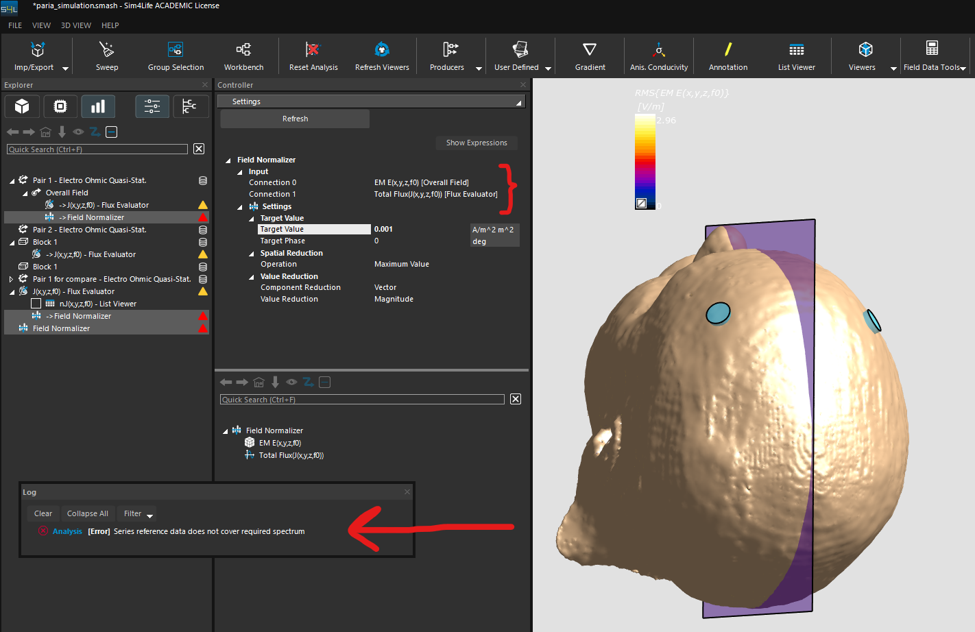
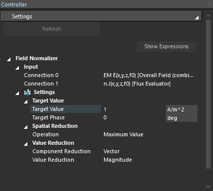
Hi, I followed the steps you described in this post to obtain the flux between two electodes in my simulation. The resulted Total Flux is (-1.22514 mA/m^2 m^2). I want to nolmalize the E-field in my simulation to have the current of 1 mA/m^2 m^2 between the electrodes. Could you please guide me on how to do that using the "Field Normalizer" at field data tools section?As seen in the attached picture, when I refresh the Field Normalizer, I get error.
-
@halder Thank you for your response. I want the total current of 1 mA flowing between my two electrodes. In this case, I should put the target value as (1 mA/area of the plane I have drawn between two electrodes)?
since my plane area is 182mm*220mm, then I should select the target value to be 0.024975 A/m2. Is this the correct approach? -
C Cindy645 referenced this topic on
-
Assume we have an LF simulation with two electrodes, at + and - 1V, respectively, as shown in the voxel view below. We want to compute the total current flowing between the two electrodes.
We start by creating a plane that cut through the computational domain, with each electrode in either part of the plane:
We then use the Flux Evaluator to compute the total current flowing through the plane:
@Sylvain Hi Sylvain! Thanks for sharing the method. I tried it in this very simple structure but get unexpected result for current density. Also available at my post here https://forum.zmt.swiss/post/2071.
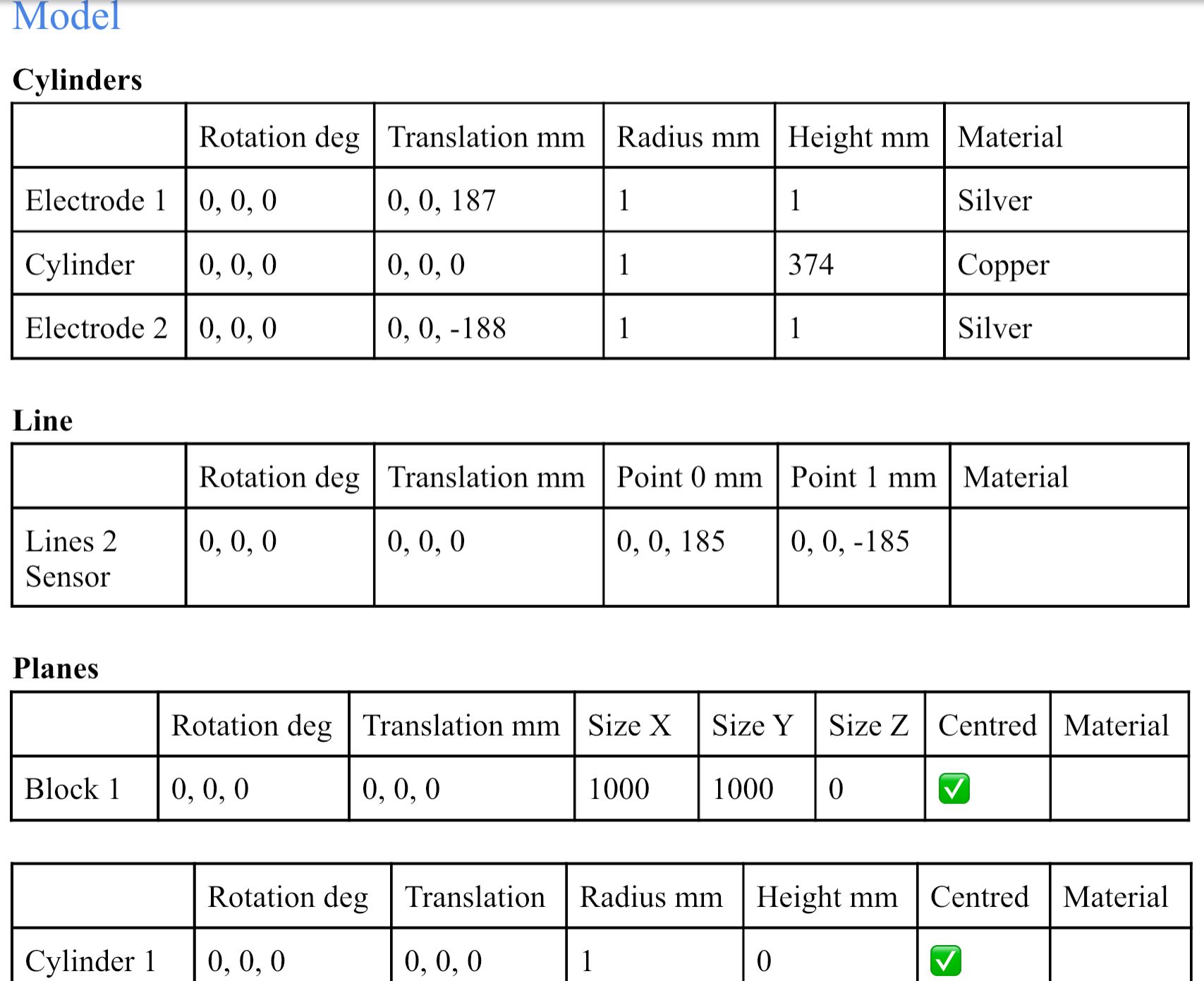
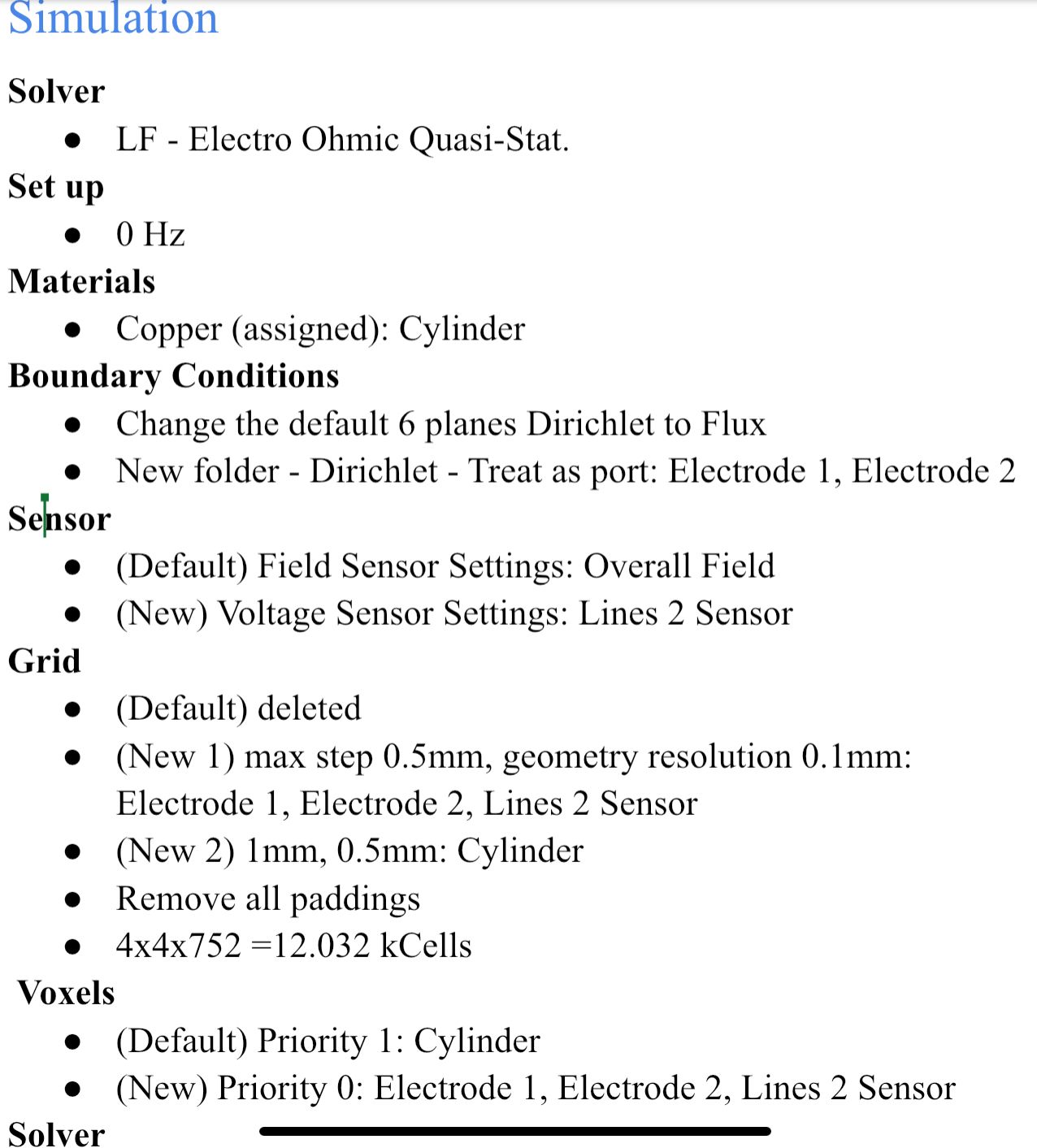
I use the following very simple structure to test whether I am using the LF Ohmic Quasi-Static Solver correctly. The voltage comes out as expected but the current (density) is incorrect. I have these three electrodes of the same radius (1mm) stacking together (touching each other) in an electrode-cylinder-electrode configuration. I want to apply to a 2V (+1V top, -1V bottom) to the two silver electrodes and achieve a 1 kA current through. So I chose the cylinder material (copper) and length such that the resistance is 2 mOhm.
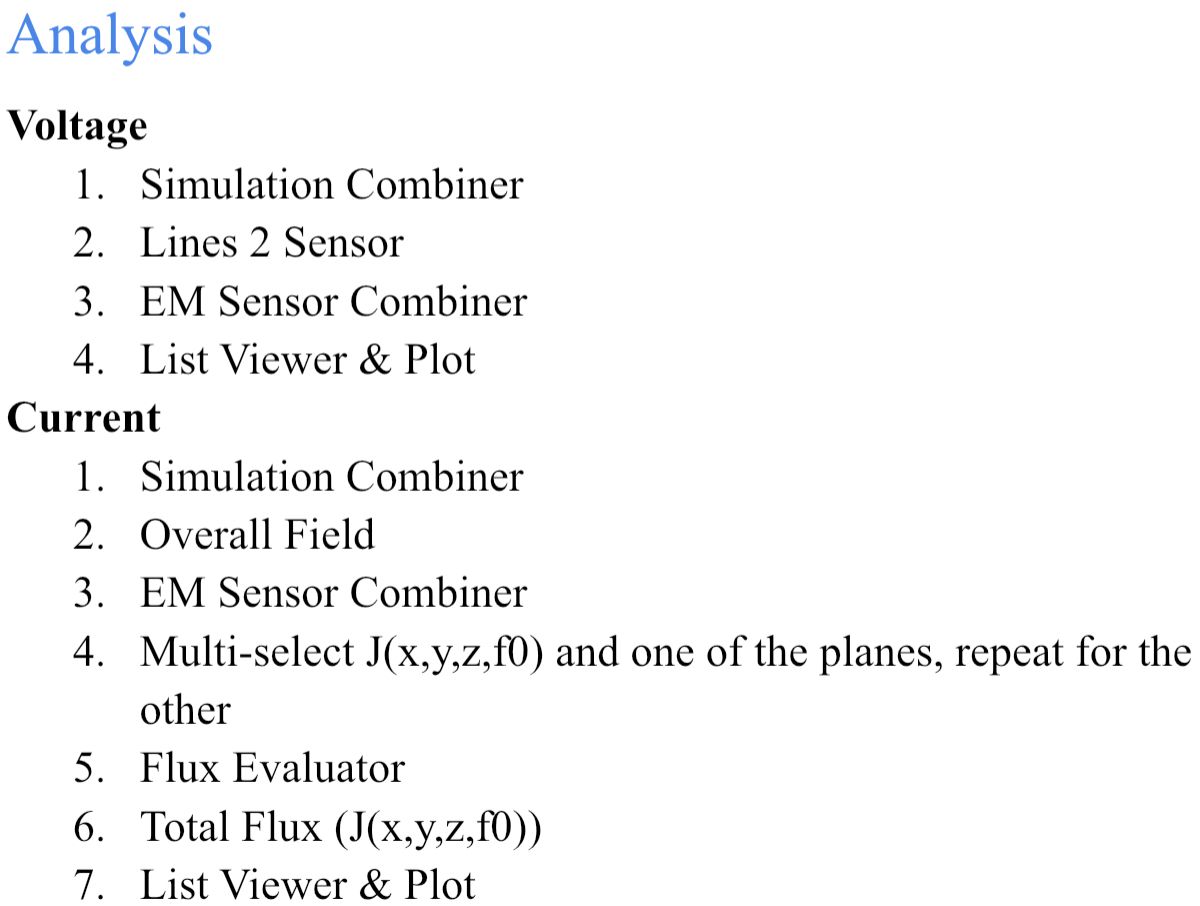
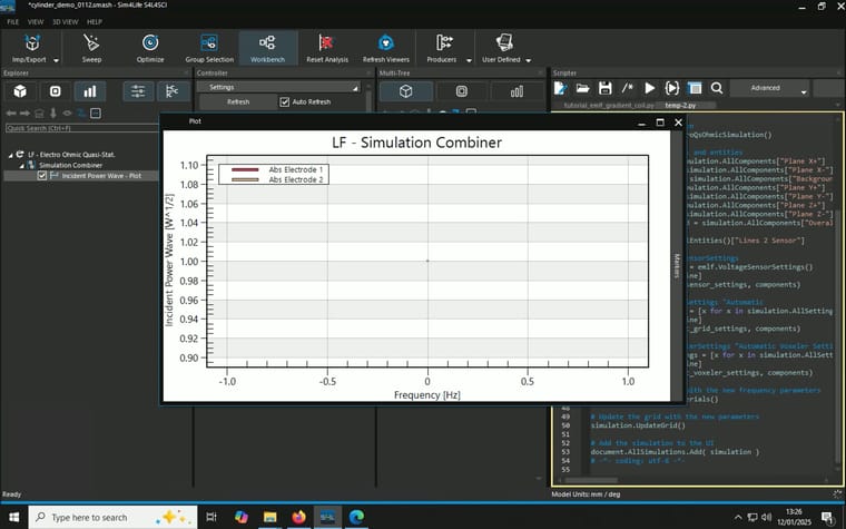
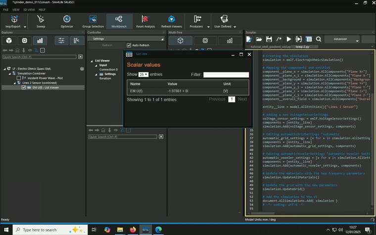
After running the simulation, where I place a line as voltage sensor (it runs from 2mm offset from the top electrode to 2mm offset from the bottom electrode, in the centre), it gives a value of -1.9786V as expected.
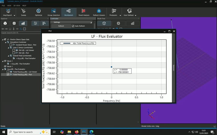
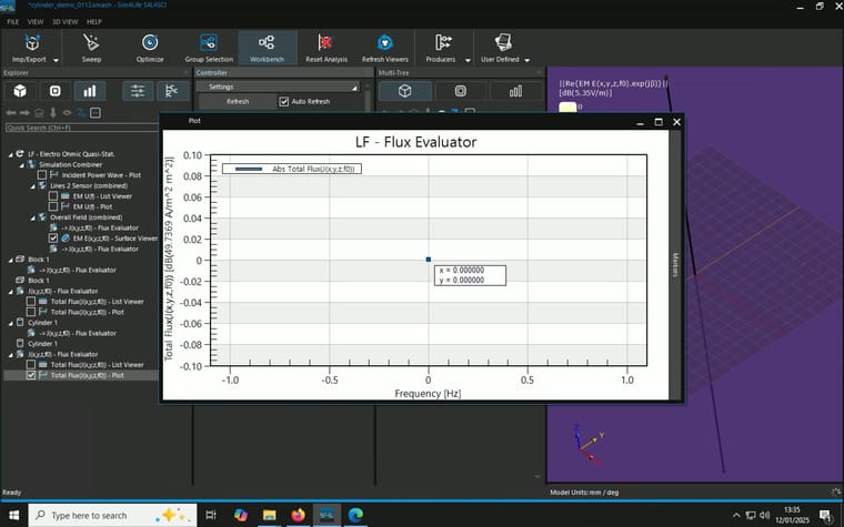
When I combine the J(x,y,z,f0) from the overall field and a plane I created and use flux evaluator to measure total current density as described here, unexpected resutls occur. I tried two different planes and they gave different results::- A block with 0mm thickness and 1m x 1m in area in the middle of the cylinder parallel to the electrodes, result: 1 A/m^2, multiply by the area gives 1A
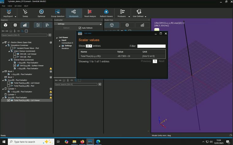
- A cylinder with 0mm thickness and 1mm in radius in the middle of the cylinder parallel to the elctrodes, resutls: 49.7369 A/m^2, multiply by the area gives 0.156mA
(P.S. why the current density has a unit of [A/m^2 m^2]?)
Model, Simulation and Analysis details are summaried in the screenshots attached.
-
Hi, sorry to bother you. Do you happen to know how to calculate the current absorbed by the electrodes and the impedance?
Hello! It looks like you're interested in this conversation, but you don't have an account yet.
Getting fed up of having to scroll through the same posts each visit? When you register for an account, you'll always come back to exactly where you were before, and choose to be notified of new replies (either via email, or push notification). You'll also be able to save bookmarks and upvote posts to show your appreciation to other community members.
With your input, this post could be even better 💗
Register Login