Once you have whatever you need as a numpy array I suggest you use one of these functions to visualize it within Sim4Life
import s4l_v1 as s4l
import s4l_v1.document as document
import s4l_v1.analysis as analysis
import s4l_v1.model as model
def visualizeArray(data, x=None,y=None,z=None, unit_name="", unit="", name="", scaling = 1.0, visualize_max = False, scalarrange = None, visualize_isosurface = False, debug = False):
"""
Create field in postpro to visualize data, if no axis provided
then they are automatically assigned based on number of elements in data
visualizeArray(data, x=None,y=None,z=None,unit_name="", unit="", name="", scaling = 0.001, goToMax = False)
data - numpy array - 3D numpy array
x - numpy array - 1D numpy array of x axis coordinates
y - numpy array - 1D numpy array of y axis coordinates
z - numpy array - 1D numpy array of z axis coordinates
unit_name - string - unit name to be displayed
unit - string - unit to be displayed
name - string - name of field in postpro
scaling - float - scaling factor for axes (default 0.001)
goToMax - boolean - visualize slice field viewer of maximum in array
visualize_slice
scalarrange
visualize_isosurface
isosurface_value
debug
"""
if x is None:
x = np.arange(data.shape[0]+1)*.001
if y is None:
y = np.arange(data.shape[1]+1)*.001
if z is None:
z = np.arange(data.shape[2]+1)*.001
grid = analysis.core.RectilinearGrid()
grid.XAxis = np.array(x)*scaling
grid.YAxis = np.array(y)*scaling
grid.ZAxis = np.array(z)*scaling
field = analysis.core.DoubleFieldData()
field.Grid = grid
if data.size == (len(x) * len(y) * len(z)):
field.ValueLocation = analysis.core.eValueLocation.kNode
elif data.size == (len(x)-1) * (len(y)-1) * (len(z)-1):
field.ValueLocation = analysis.core.eValueLocation.kCellCenter
else:
print "ERROR: Grid and Data don't match"
return False
field.NumberOfComponents = 1
field.NumberOfSnapshots = 1
field.Quantity.Unit = s4l.Unit(unit)
field.Quantity.Name = unit_name
# Note: memory layout is such that x is fastest, z slowest dimension
values = data.ravel('F')
values = values.astype(np.float64)
field.SetField( 0, values )
assert field.Check()
producer = analysis.core.TrivialProducer()
if name != "":
producer.Description = name
producer.SetDataObject(field)
if visualize_max:
sfv = analysis.viewers.SliceFieldViewer()
sfv.Inputs[0].Connect( producer.Outputs[0] )
sfv.Slice.Plane = sfv.Slice.Plane.enum.XY
sfv.Update(0)
sfv.GotoMaxSlice()
sfv.Update(0)
document.AllAlgorithms.Add(sfv)
sfv = analysis.viewers.SliceFieldViewer()
sfv.Inputs[0].Connect( producer.Outputs[0] )
sfv.Slice.Plane = sfv.Slice.Plane.enum.YZ
sfv.Update(0)
sfv.GotoMaxSlice()
sfv.Update(0)
document.AllAlgorithms.Add(sfv)
sfv = analysis.viewers.SliceFieldViewer()
sfv.Inputs[0].Connect( producer.Outputs[0] )
sfv.Slice.Plane = sfv.Slice.Plane.enum.XZ
sfv.Update(0)
sfv.GotoMaxSlice()
sfv.Update(0)
document.AllAlgorithms.Add(sfv)
if visualize_isosurface:
iso_surface_viewer = analysis.viewers.IsoSurfaceViewer()
iso_surface_viewer.Inputs[0].Connect( producer.Outputs[0] )
iso_surface_viewer.Data.Mode = iso_surface_viewer.Data.Mode.enum.QuantityRealModulus #H CHECK - maybe should just use default (delete this line)
iso_surface_viewer.Visualization.ScalarBarVisible = False
iso_surface_viewer.UpdateAttributes()
iso_surface_viewer.Update(0)
document.AllAlgorithms.Add(iso_surface_viewer)
document.AllAlgorithms.Add(producer)
return producer
def visualizeComplexArray(data, x=None,y=None,z=None, unit_name="", unit="", name="", scaling = 1.0, visualize_max = False, scalarrange = None, visualize_isosurface = False, debug = False):
"""
Create field in postpro to visualize data, if no axis provided
then they are automatically assigned based on number of elements in data
visualizeArray(data, x=None,y=None,z=None,unit_name="", unit="", name="", scaling = 0.001, goToMax = False)
data - numpy array - 3D numpy array
x - numpy array - 1D numpy array of x axis coordinates
y - numpy array - 1D numpy array of y axis coordinates
z - numpy array - 1D numpy array of z axis coordinates
unit_name - string - unit name to be displayed
unit - string - unit to be displayed
name - string - name of field in postpro
scaling - float - scaling factor for axes (default 0.001)
goToMax - boolean - visualize slice field viewer of maximum in array
visualize_slice
scalarrange
visualize_isosurface
isosurface_value
debug
"""
if x is None:
x = np.arange(data.shape[0]+1)*.001
if y is None:
y = np.arange(data.shape[1]+1)*.001
if z is None:
z = np.arange(data.shape[2]+1)*.001
grid = analysis.core.RectilinearGrid()
grid.XAxis = np.array(x)*scaling
grid.YAxis = np.array(y)*scaling
grid.ZAxis = np.array(z)*scaling
field = analysis.core.ComplexDoubleFieldData()
field.Grid = grid
if data.size == (len(x) * len(y) * len(z)):
field.ValueLocation = analysis.core.eValueLocation.kNode
elif data.size == (len(x)-1) * (len(y)-1) * (len(z)-1):
field.ValueLocation = analysis.core.eValueLocation.kCellCenter
else:
print "ERROR: Grid and Data don't match"
return False
field.NumberOfComponents = 1
field.NumberOfSnapshots = 1
field.Quantity.Unit = s4l.Unit(unit)
field.Quantity.Name = unit_name
# Note: memory layout is such that x is fastest, z slowest dimension
values = data.ravel('F')
#values = values.astype(np.complex64)
field.SetField( 0, values )
assert field.Check()
producer = analysis.core.TrivialProducer()
if name != "":
producer.Description = name
producer.SetDataObject(field)
if visualize_max:
sfv = analysis.viewers.SliceFieldViewer()
sfv.Inputs[0].Connect( producer.Outputs[0] )
sfv.Slice.Plane = sfv.Slice.Plane.enum.XY
sfv.Update(0)
sfv.GotoMaxSlice()
sfv.Update(0)
document.AllAlgorithms.Add(sfv)
sfv = analysis.viewers.SliceFieldViewer()
sfv.Inputs[0].Connect( producer.Outputs[0] )
sfv.Slice.Plane = sfv.Slice.Plane.enum.YZ
sfv.Update(0)
sfv.GotoMaxSlice()
sfv.Update(0)
document.AllAlgorithms.Add(sfv)
sfv = analysis.viewers.SliceFieldViewer()
sfv.Inputs[0].Connect( producer.Outputs[0] )
sfv.Slice.Plane = sfv.Slice.Plane.enum.XZ
sfv.Update(0)
sfv.GotoMaxSlice()
sfv.Update(0)
document.AllAlgorithms.Add(sfv)
if visualize_isosurface:
iso_surface_viewer = analysis.viewers.IsoSurfaceViewer()
iso_surface_viewer.Inputs[0].Connect( producer.Outputs[0] )
iso_surface_viewer.Data.Mode = iso_surface_viewer.Data.Mode.enum.QuantityRealModulus #H CHECK - maybe should just use default (delete this line)
iso_surface_viewer.Visualization.ScalarBarVisible = False
iso_surface_viewer.UpdateAttributes()
iso_surface_viewer.Update(0)
document.AllAlgorithms.Add(iso_surface_viewer)
document.AllAlgorithms.Add(producer)
return producer
def visualize2DArray(data, x=None,y=None,z=None, unit_name="", unit="", name="", scaling = 1., visualize_slice = False, scalarrange = None, visualize_isosurface = False, isosurface_value = None, debug = False):
"""
Create field in postpro to visualize data, if no axis provided
then they are automatically assigned based on number of elements in data
visualize2DArray(data, x=None,y=None,z=None, unit_name="", unit="", name="", scaling = 0.001, visualize = False, scalarrange = None)
data - numpy array - 3D numpy array
x - numpy array - 1D numpy array of x axis coordinates
y - numpy array - 1D numpy array of y axis coordinates
z - numpy array - 1D numpy array of z axis coordinates
unit_name - string - unit name to be displayed
unit - string - unit to be displayed
name - string - name of field in postpro
scaling - float - scaling factor for axes (default 0.001)
visualize - bool - automatically extract field
"""
from numpy import newaxis
# Deal with dimension of data
if data.ndim == 2:
data = data[:,:,newaxis]
elif data.ndim < 2 or data.ndim > 3:
print "Data Dimensions Error"
return
# Deal with scalar axis by turning into array
if np.isscalar(x):
x = [x]
elif np.isscalar(y):
y = [y]
elif np.isscalar(z):
z = [z]
#If axes are not set, then make axes
if x is None:
x = np.arange(data.shape[0]+1)*.001
if y is None:
y = np.arange(data.shape[1]+1)*.001
if z is None:
z = np.arange(data.shape[2]+1)*.001
# Deal with monotonically decreasing axes
if np.all(np.diff(x) < 0) and np.size(x) > 1:
x = x[::-1]
data = data[::-1]
if debug == True:
print "Warning: Monotonically decreasing x axes"
if np.all(np.diff(y) < 0) and np.size(y) > 1:
y = y[::-1]
data = data[:,::-1]
if debug == True:
print "Warning: Monotonically decreasing y axes"
if np.all(np.diff(z) < 0) and np.size(z) > 1:
z = z[::-1]
data = data[:,:,::-1]
if debug == True:
print "Warning: Monotonically decreasing z axes"
grid = analysis.core.RectilinearGrid()
grid.XAxis = np.array(x)*scaling
grid.YAxis = np.array(y)*scaling
grid.ZAxis = np.array(z)*scaling
field = analysis.core.DoubleFieldData()
field.Grid = grid
if data.size == (len(x) * len(y) * len(z)):
field.ValueLocation = analysis.core.eValueLocation.kNode
elif data.size == (len(x)-1) * (len(y)-1) * (len(z)-1):
field.ValueLocation = analysis.core.eValueLocation.kCellCenter
else:
print "ERROR: Grid and Data don't match"
return
field.NumberOfComponents = 1
field.NumberOfSnapshots = 1
field.Quantity.Unit = s4l.Unit(unit)
field.Quantity.Name = unit_name
# Note: memory layout is such that x is fastest, z slowest dimension
values = data.ravel('F')
values = values.astype(np.float64)
field.SetField( 0, values )
assert field.Check()
producer = analysis.core.TrivialProducer()
if name != "":
producer.Description = name
producer.SetDataObject(field)
# Adding a SliceSurfaceViewer
if visualize_slice:
sfv = analysis.viewers.SliceFieldViewer()
sfv.Inputs[0].Connect( producer.Outputs[0] )
if len(x) == 1:
sfv.Slice.Plane = sfv.Slice.Plane.enum.YZ
elif len(y) == 1:
sfv.Slice.Plane = sfv.Slice.Plane.enum.XZ
elif len(z) == 1:
sfv.Slice.Plane = sfv.Slice.Plane.enum.XY
sfv.Visualization.ScalarBarVisible = False
if scalarrange != None:
sfv.ScalarRange = scalarrange
sfv.Update(0)
document.AllAlgorithms.Add(sfv)
# Adding a IsoSurfaceViewer
if visualize_isosurface:
iso_surface_viewer = analysis.viewers.IsoSurfaceViewer()
iso_surface_viewer.Inputs[0].Connect( producer.Outputs[0] )
if isosurface_value is not None:
iso_surface_viewer.IsoValues = (isosurface_value,)
iso_surface_viewer.Data.Mode = iso_surface_viewer.Data.Mode.enum.QuantityRealModulus #H CHECK - maybe should just use default (delete this line)
iso_surface_viewer.Visualization.ScalarBarVisible = False
iso_surface_viewer.UpdateAttributes()
iso_surface_viewer.Update()
if scalarrange != None:
iso_surface_viewer.ScalarRange = scalarrange
iso_surface_viewer.UpdateAttributes()
iso_surface_viewer.Update()
document.AllAlgorithms.Add(iso_surface_viewer)
document.AllAlgorithms.Add(producer)
return producer
to use it then you would just need to do:
visualize2DArray(my_data, x_axis, y_axis, z_coordinate)
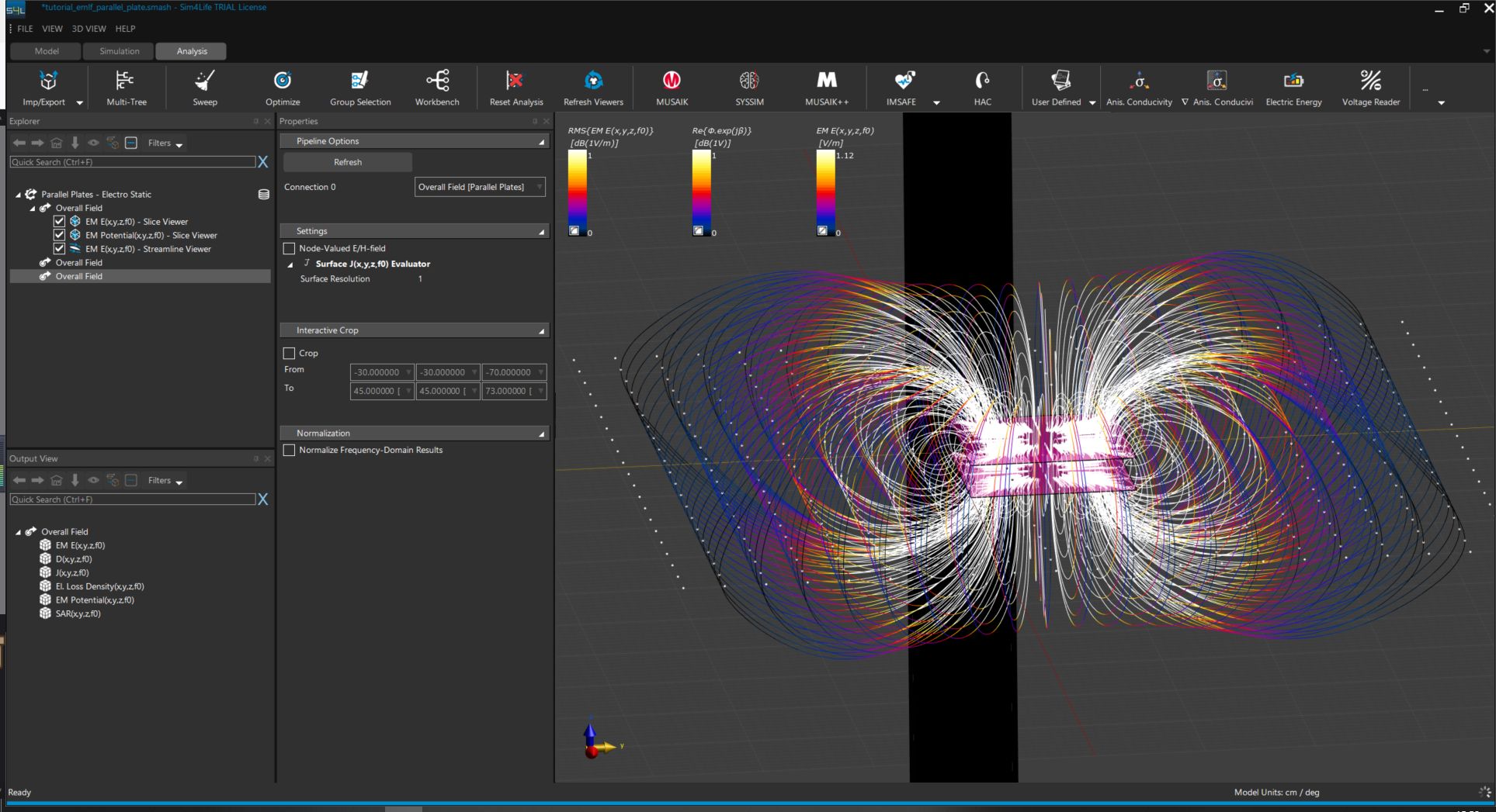
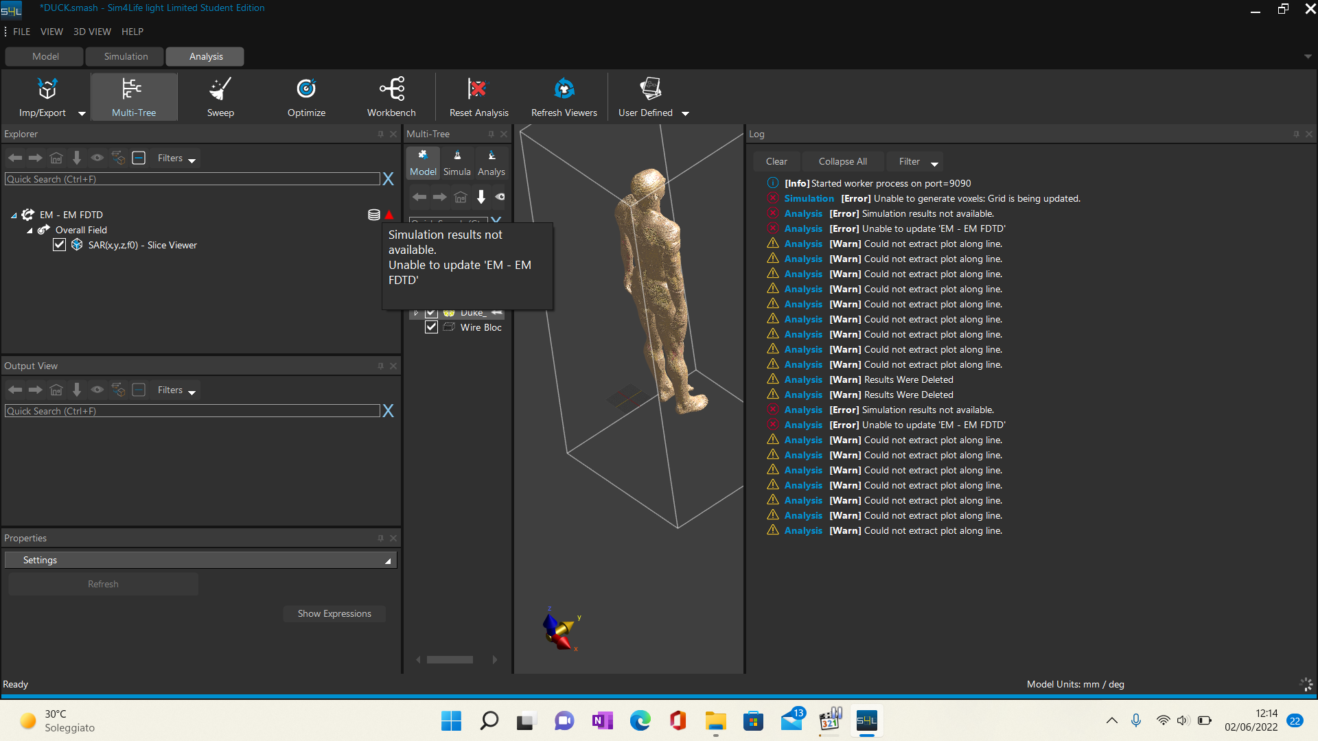
and then it should show up in the Postpro / Analysis tab for you to work this