I tried to reproduce this doing the following. I create three entities
a cylinder
copy it and convert the copy to a triangle mesh
generate an unstructured tetrahedral mesh
Then I drag these entities to the Analysis (ModelToGridFilter in Python API).
I tried to use the surface viewer, but since they have no fields, nothing is displayed (this changed since 7.0 or before - it used to display a white surface).
To generate a field I used the Calculator, and added expressions like coordsY*jHat, i.e. (0, coordsY, 0) where coordsY is the y-coordinate from the points in the geometry.
Create a vector viewer for each (from the left: Solid Body, TriangleMesh, UnstructuredMesh). The third one samples vector values using Line/Plane/Box sources.
[image: 1749109986009-d5bc2f0e-af54-4fca-8265-1431e94207ca-image.png]
To get the vectors on the surface of the UnstructuredMesh, I had to first extract the surface, via Field Data Tools -> Surface Filter
[image: 1749110185730-938040d9-2fcf-4cad-a42e-7c2f0d4592ec-image.png]
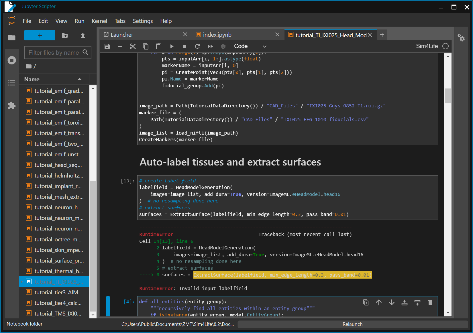
The generated Python ("To Python' in context menu) script for item 5 was:
# This script was auto-generated by Sim4Life version 8.2.0.16890
import numpy
import s4l_v1.analysis as analysis
import s4l_v1.document as document
import s4l_v1.model as model
import s4l_v1.units as units
from s4l_v1 import ReleaseVersion
from s4l_v1 import Unit
try:
# Define the version to use for default values
ReleaseVersion.set_active(ReleaseVersion.version8_2)
# Creating the analysis pipeline
# Adding a new ModelToGridFilter
inputs = []
model_to_grid_filter = analysis.core.ModelToGridFilter(inputs=inputs)
model_to_grid_filter.Name = "Cylinder 3"
model_to_grid_filter.Entity = model.AllEntities()["Cylinder 3"]
model_to_grid_filter.UpdateAttributes()
document.AllAlgorithms.Add(model_to_grid_filter)
# Adding a new FieldCalculator
inputs = [model_to_grid_filter.Outputs["Unstructured Grid"]]
field_calculator = analysis.field.FieldCalculator(inputs=inputs)
field_calculator.Expression = u"coordsZ*kHat"
field_calculator.UpdateAttributes()
document.AllAlgorithms.Add(field_calculator)
# Adding a new FieldSurfaceFilter
inputs = [field_calculator.Outputs["Result(x,y,z)"]]
field_surface_filter = analysis.field.FieldSurfaceFilter(inputs=inputs)
field_surface_filter.UpdateAttributes()
document.AllAlgorithms.Add(field_surface_filter)
# Adding a new VectorFieldViewer
inputs = [field_surface_filter.Outputs["Result(x,y,z)"]]
vector_field_viewer = analysis.viewers.VectorFieldViewer(inputs=inputs)
vector_field_viewer.Data.Phase = u"0°"
vector_field_viewer.Vector.Plane.PlaneCenter = numpy.array([0.05300000309944153, -0.03099999949336052, 0.012000000104308128])
vector_field_viewer.UpdateAttributes()
document.AllAlgorithms.Add(vector_field_viewer)
except Exception as exc:
import traceback
traceback.print_exc()
# Reset active version to default
ReleaseVersion.reset()
raise(exc)