Hi Marcus,
This doesn't appear to be related to Windows Defender.
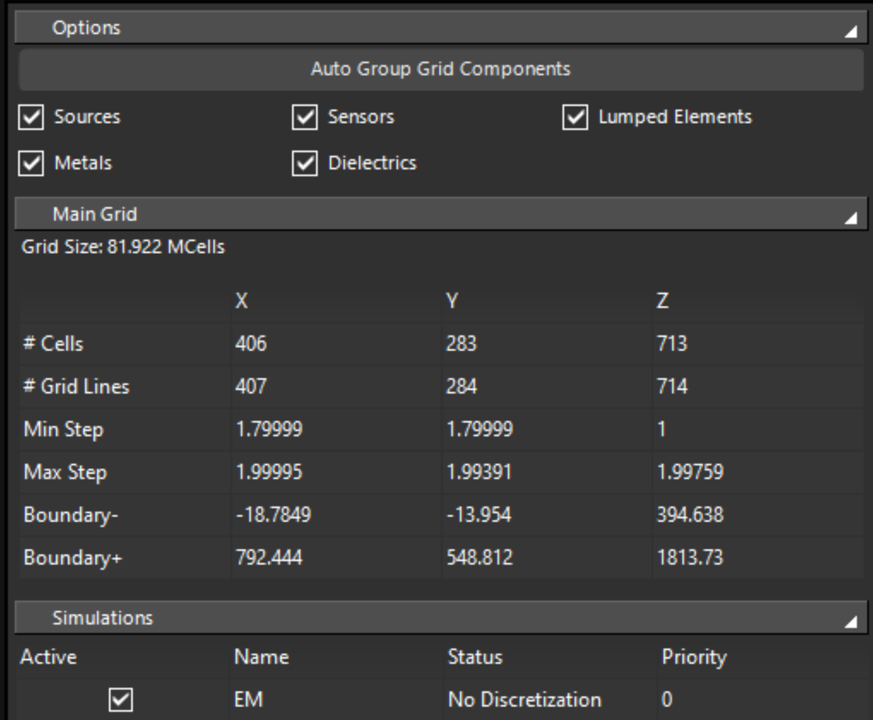
However, from the log you pasted, it is not exactly the tutorial of TMS. The grid is different than what is described in the tutorial, and there is an additional object in the simulation "Reference_Plane".
Something in your setup is not correct anymore and cause the solver to fail. With the amount of information I have here, I cannot suggest a solution.
Please try to run the tutorial as it is (maybe open the project file and run it, instead of building it from scratch), and see if this one fails too.
Best,
Habib