Hi, I'm trying to simulate a synapse between two identical neuron models, imported from the same .hoc file.
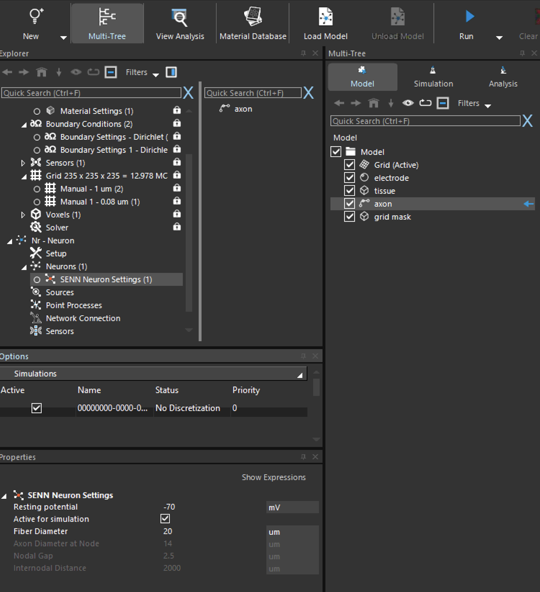
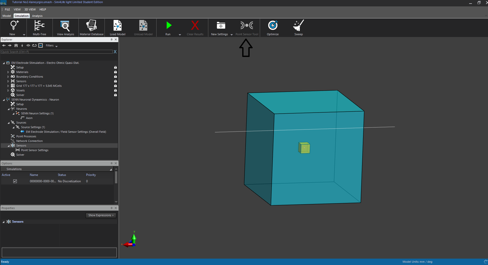
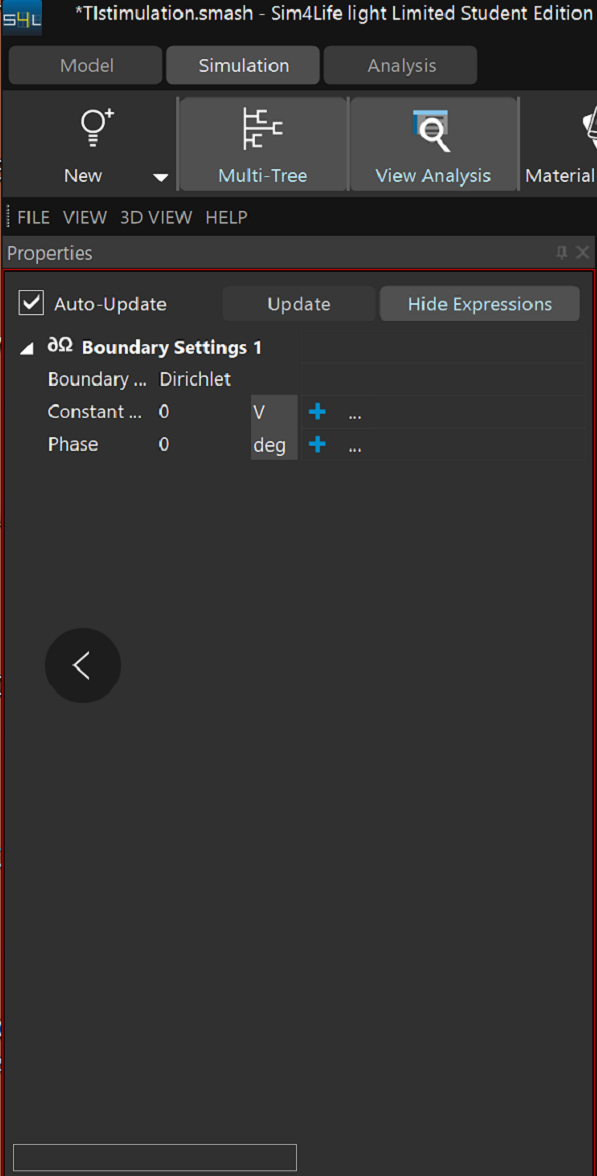
I set the simulation as follow (see screenshot):
-both neuron have the same HOC Model Settings
-The first neuron "L23_PC_cADpyr229_1", pre-synaptic, has an IClamp on its soma
-The second neuron "L23_PC-cADpyr229_2", post-synaptic, has a Exp2Syn point process on dendrite 9
-The network connection was created drag & dropping the first neuron's model and the Exp2Syn point process of the second neuron in the network connection settings
[image: 1778756649765-f7472fbe-2fe9-4244-9297-34d7a1f29c16-image.png]
If I try to run the simulation I get the error messages:
Simulation : [Error] Failed to create neuron group ids.
Error : Failed to write the input file
Error : Unable to start simulation: failed to write input files.
How can I solve this error?
I already tried using different neurons from different .hoc files.
Thank you in advance